Wing tip device

a technology of wing tip and wing tip, which is applied in the direction of airflow influencers, applications, manufacturing tools, etc., can solve the problems of reducing the wing span of the resulting flight shape, affecting the performance of the approach, and no longer being optimal, so as to reduce the interference drag effect, increase the local dihedral curvature, and maintain the constant radius of curvature

Active Publication Date: 2015-05-19
AIRBUS OPERATIONS LTD +1
View PDF152 Cites 10 Cited by
  • Summary
  • Abstract
  • Description
  • Claims
  • Application Information

AI Technical Summary

Benefits of technology

[0018]The invention is advantageous in that the lower wing-like element acts to offset at least some of the decrease in wing span that occurs due to aeroelastic deformation in the flight shape, whilst the upper and lower wing-like elements may still be optimised to meet any applicable span constraints in the ground shape. The addition of the lower element to a wing tip device comprising only an upper wing-like element (e.g. a winglet) has been shown to reduce drag on the wing / wing tip device combination by around a further 1.9% overall, with a vortex drag reduction of around a further 25 to 40% relative to that provided by the upper element alone.
[0032]In yet another embodiment, the upper wing-like element may include a substantially planar portion and a non-planar curved wing tip extension adapted to smoothly blend the outboard end of the wing into the substantially planar portion of the upper wing-like element. The upper element may be a winglet blended into the wing by a non-planar wing tip extension portion. The non-planar wing tip extension portion may have increasing curvature of local dihedral in the outboard direction. The wing tip extension portion helps to further reduce interference drag effects compared to a blended winglet with a constant radius transition.

Problems solved by technology

However, due to the bend induced on the wing shape from aeroelastic effects during flight, the wing span of the resulting flight shape is usually reduced and is therefore no longer optimal.
This traditional approach therefore carries a performance shortfall.
This problem becomes even more appreciable with greater use of relatively flexible wings to reduce structural weight, which tend to result in increased wing bending under aerodynamic load when compared to more rigid designs.

Method used


Image

  • Wing tip device
  • Wing tip device
  • Wing tip device

Examples


first embodiment

[0058]FIG. 3 illustrates an aircraft wing 101 having a planar upper winglet 104 and a planar lower winglet 107. The upper winglet 104 is fixed to the outboard end 103 of the wing 101. The wing 101 defines a wing plane 108. The upper winglet 104 projects upwardly with respect to the wing plane 108. The upper winglet 104 has a tip 109 and a root 110. The lower winglet has a tip 111 and a root 112. The lower winglet root chord 112 intersects with the upper winglet 104 and the lower winglet 107 projects downwardly from this intersection. The upper and lower winglets 104, 107 each have a leading edge and a trailing edge and the trailing edges are adjacent at the intersection. FIG. 3a) illustrates the wing 101 in its ground shape where the tip 109 of the upper winglet 104 and the tip 111 of the lower winglet 107 are coincident at the span limit 105. FIG. 3b) illustrates the wing 101 in its deformed flight shape and shows how a potential loss in span 106 due to the upper winglet 104 is mi...

second embodiment

[0061]FIG. 7 illustrates an aircraft wing 201 having a planar upper winglet 204 and a non planar lower winglet 207. The wing 201 defines a wing plane 208 and the upper winglet 204 projects upwardly with respect to the wing plane 208. The upper winglet 204 is fixed to the outboard end 203 of the wing 201. The lower winglet 207 has a root chord 212 which intersects with the upper winglet 204. The lower winglet 207 projects downwardly from the intersection. The upper winglet 204 has a tip 209 and a root 210. The lower winglet 207 has a tip 211 that is coincident in the spanwise direction with the tip 209 at the span limit 205. The upper and lower winglets 204, 207 each have a leading edge and a trailing edge and the trailing edges are adjacent at the intersection. The wing 201 is illustrated in FIG. 7 in its ground shape where the span limit 205 is enforced.

[0062]The lower winglet 207 has increasing curvature of local anhedral from root 212 to tip 211. The lower winglet 207 may have a...

third embodiment

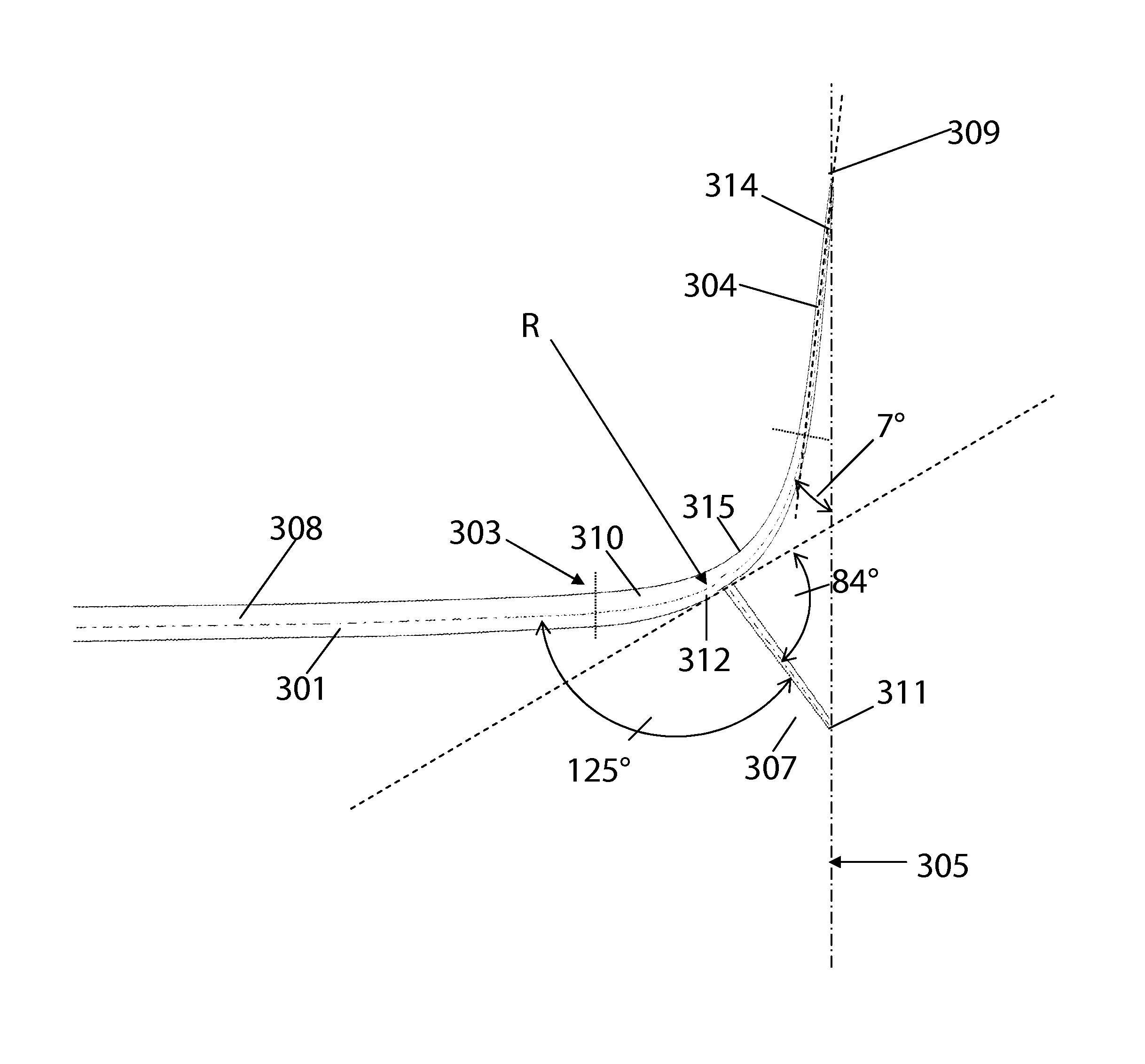
[0064]FIG. 8 illustrates an aircraft wing 301 having a blended upper winglet 304 and a planar lower winglet 307. The wing 301 has an outboard end 303 to which is fixed the blended upper winglet 304. The upper winglet 304 has a tip 309 and a root 310. The upper winglet 304 is fixed to the outboard end 303 of the wing 301 by its root end 310. The upper winglet 304 has a substantially planar portion 314 and an arcuate transition portion 315. The transition portion 315 is adapted to smoothly blend the outboard end 303 of the wing 301 into the substantially planar portion 314. The arcuate transition portion 315 has a substantially constant radius of curvature R.

[0065]The lower winglet 307 is fixed to the lower surface of the transition portion 315 of the upper winglet 304. The lower winglet has a tip 311 and a root 312. The root chord of the lower winglet 307 intersects with the upper winglet 304 and the lower winglet projects downwardly from the intersection. The upper and lower wingle...


PUM

PropertyMeasurementUnit
included angleaaaaaaaaaa

Abstract

A wing tip device for fixing to the outboard end of a wing, the wing defining a wing plane, includes: an upper wing-like element projecting upwardly with respect to the wing plane and having a trailing edge; and a lower wing-like element fixed with respect to the upper wing-like element and having a root chord and a trailing edge, the lower wing-like element root chord intersecting with the upper wing-like element, and the lower wing-like element projecting downwardly from the intersection. The upper wing-like element is larger than the lower wing-like element and the trailing edge of the lower wing-like element is adjacent the trailing edge of the upper wing-like element at the intersection. An included angle between the upper and lower wing-like elements at the intersection is less than, or equal to, 160 degrees.

Description

RELATED APPLICATIONS[0001]The present application is a National Phase of International Application Number PCT / EP2011 / 061552, filed Jul. 7, 2011, and claims priority from, British Application Number 1011843.8, filed Jul. 14, 2010.FIELD OF THE INVENTION[0002]The present invention relates to a wing tip device for fixing to the outboard end of a wing. Also, a wing with the wing tip device; an aircraft with the wing; a method of fitting, or retro-fitting, the wing tip device to a wing; a method of modifying an existing wing tip device; and a method of operating a wing with the wing tip device.BACKGROUND OF THE INVENTION[0003]A wing tip device is attached to the outboard end of a wing to reduce induced drag on the wing. In the case of e.g. an aircraft wing this can lead to improved fuel efficiency and reduced carbon emissions. Wing tip devices can take a variety of forms.[0004]A winglet is a wing-like element that extends from the wing tip. A winglet may extend upwardly or downwardly from...

Claims


Application Information

Patent Timeline
Patent Type & Authority Patents(United States)
IPC IPC(8): B64C23/06
CPCB64C23/065Y10T29/49716Y02T50/164B64C3/10B64C5/08B64C23/069Y02T50/10B64C23/06B64C3/58
Inventor WRIGHT, CHRISTOPHERCHU, JAMES K.HIMISCH, JAN
Owner AIRBUS OPERATIONS LTD
Why Eureka
Try Eureka