

Explosive blast shield for buildings
a technology of explosive blast shield and building, applied in the field of shield, can solve the problems of additional property damage and personal injury
- Summary
- Abstract
- Description
- Claims
- Application Information
AI Technical Summary
Benefits of technology
Problems solved by technology
Method used
Image

Examples
first embodiment
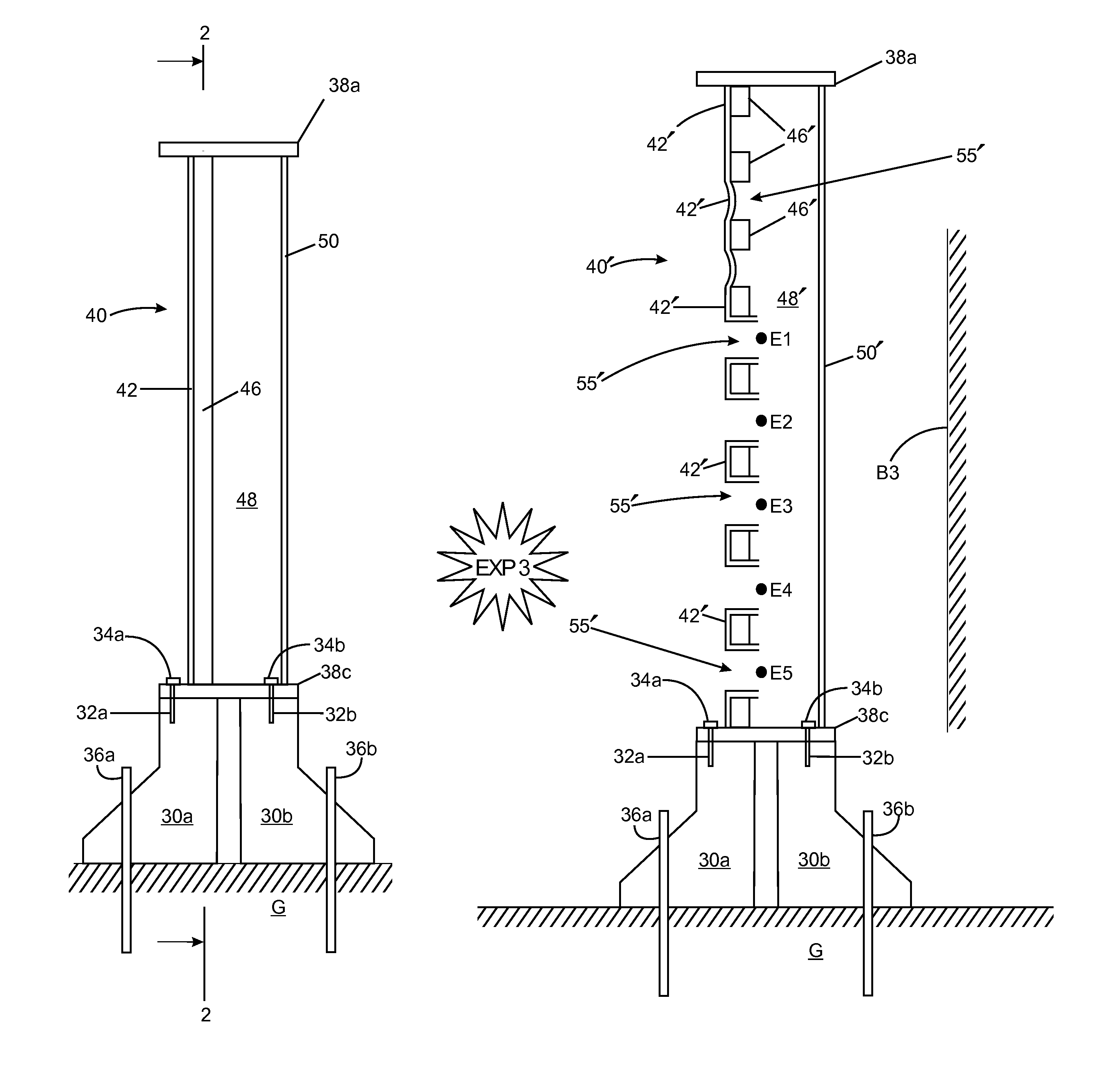
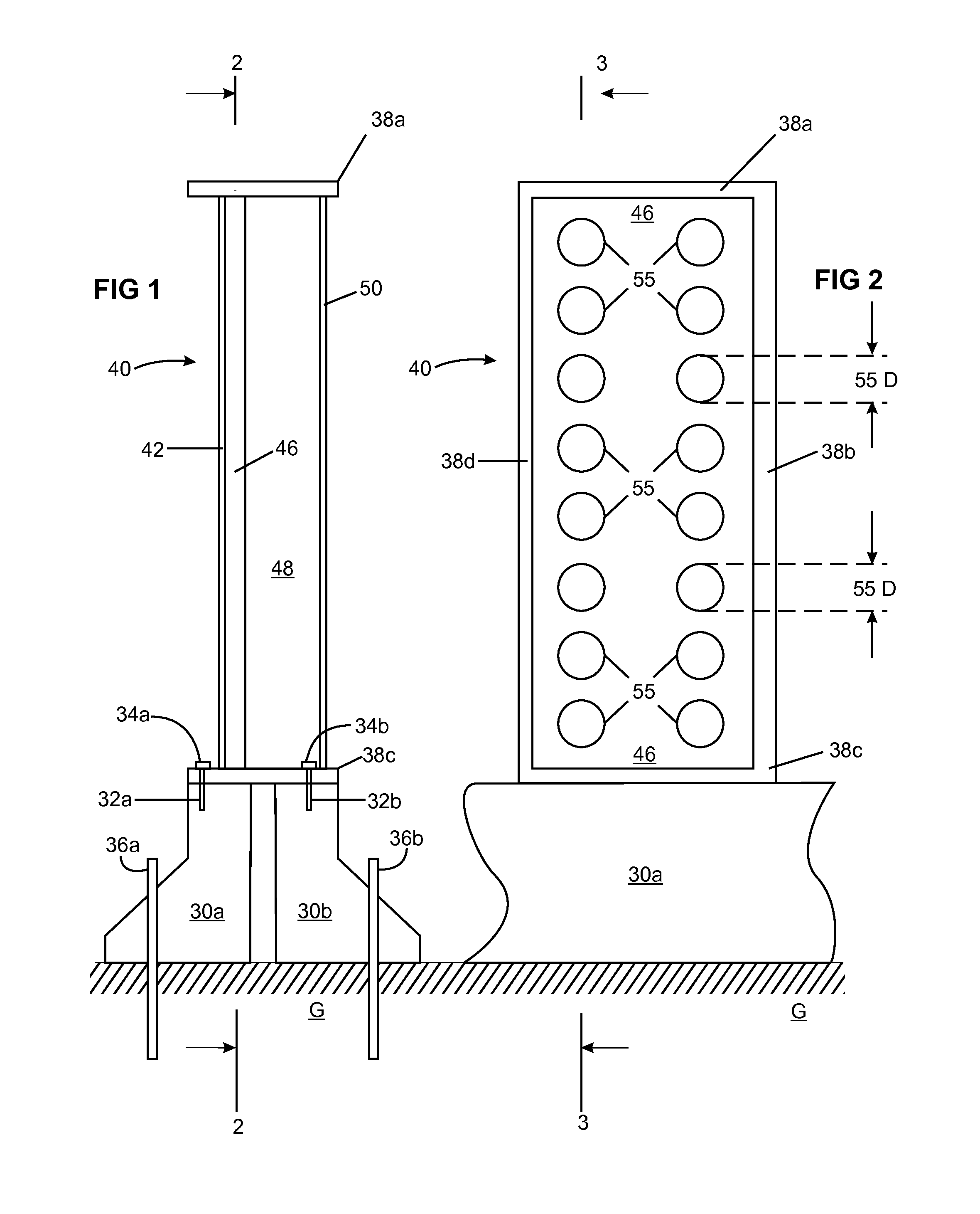
[0027]Reference is made to FIG. 1, FIGS. 1a, 1b, 1c and FIG. 2. A blast shield 40 comprises a composite panel and preferably a spall shield 50. Frame members 38a, 38b, 38c and 38d hold the spall shield 50 in laminar orientation and spaced from the composite panel 42, 46. The blast shield is the assembled combination of each individual component, i.e. element 42 (comprising 43, 44, 45), element 46 and element 50 which will be described. Blast shield 40 is mounted on and fixedly attached to a vehicle barrier shown here as Jersey barriers 30a and 30b. Heavy bolts 32a and 32b are attached to the concrete Jersey barriers which also include steel reinforcement bars (not shown) for collision integrity. Frame member 38c is fixedly attached to the Jersey barriers 30a and 30b by means of the heavy steel alloy bolts 32a and 32b and nuts 34a and 34b. Jersey barriers 30a and 30b are immobilized by steel reinforcement bars 36a and 36b driven into the ground G.
[0028]Alternative mounting of the bla...
second embodiment
[0060]In FIG. 5 and FIG. 6, blast shield 140 comprises a panel. In this embodiment there is no spall liner. Frame members 138a, 138b, 138c and 138d hold the blast shield 140 and allow mounting and fixed attachment to a vehicle barrier shown here as Jersey barriers 130a and 130b. Heavy bolts 132a and 132b are attached to the steel reinforced, concrete Jersey barriers. Frame member 138c is fixedly attached to the Jersey barriers 130a and 130b by means of heavy steel alloy bolts 132a and 132b and nuts 134a and 134b. Similarly, Jersey barriers 130a and 130b are immobilized with steel reinforcement bars 136a and 136b driven into the ground G.
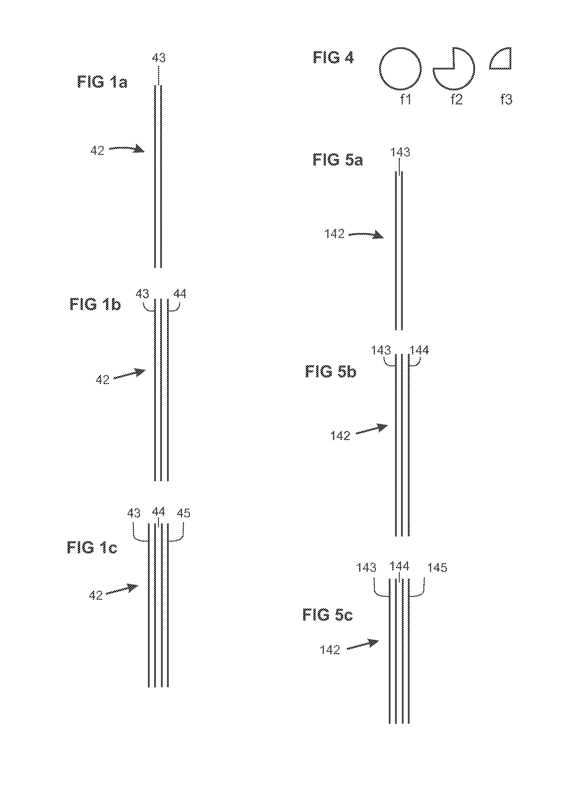
[0061]The laminar blast shield 140 comprises adjacent layers comprising a ductile strike layer 142 and a structural armor plate layer 146. Ductile strike layer 142 corresponds with the ductile strike layer 42 described above.
[0062]FIG. 5a shows ductile strike layer 142. In this embodiment, strike layer 142 is a single metallic strike surface layer 14...
example 1
Background
[0078]We investigated the blast performance of thin sheets of aluminum coated with a thin layer of Air Products VERSALINK® 1000 polyurea. The specified yield of the aluminum 5052 H32 alloy was 28 ksi. This compares with a specific yield of 51 ksi for DH-36 steel. The modulus of aluminum was ⅓ that of steel and the density was on the order of 40% of steel. The density and modulus of the aluminum were more closely aligned with the density and modulus of polyurea.
[0079]The polyurea coated aluminum sheet was supported with a structural armor plate. The support was made by cutting 2.3 inch diameter ports through the 2-inch thick by 9-square foot, HY-100 steel plate. A bevel of 45° around the diameter of each port on the surface of the plate extended the openings to 2.5 inches. This produced a structural armor plate with 49 equally spaced ports clustered at different distances from a central port. The obliquity and standoff varied with distance from the central port. The explosi...
PUM
| Property | Measurement | Unit |
|---|---|---|
| Thickness | aaaaa | aaaaa |
| Thickness | aaaaa | aaaaa |
| Thickness | aaaaa | aaaaa |
Abstract
Description
Claims
Application Information