Off-center ground return for RF-powered showerhead

a showerhead and off-center ground technology, applied in the field of off-center ground return of rf-powered showerheads, can solve the problems of undesirable asymmetry in plasma density and non-uniformity in plasma fabrication processes, and achieve the effect of improving the spatial uniformity of plasma processes, reducing the inductance of load impedance, and reducing the q of resonant circuits

Active Publication Date: 2015-05-26
APPLIED MATERIALS INC
View PDF62 Cites 9 Cited by
  • Summary
  • Abstract
  • Description
  • Claims
  • Application Information

AI Technical Summary

Benefits of technology

[0008]One advantage of the invention is that the offset toward the workpiece passageway of the first connection area on the chamber cover compensates for the asymmetry in plasma density that otherwise would be caused by the workpiece passageway, thereby enabling improved spatial uniformity of a plasma process performed in the chamber.
[0009]Another advantage of the aforesaid offset is that it reduces the inductance of the load impedance at the output of the impedance matching network, and thereby reduces the Q of the resonant circuit created by the impedance matching network in combination with the plasma chamber load. Reducing the Q has at least two important advantages. First, it reduces the peak voltage in the circuit, thereby reducing the risk of electrical arcing or component failure. Second, in the case of a fixed-reactance matching network that relies on a variable-frequency RF power supply to optimize the impedance match, a lower Q provides a wider range of load impedances that can be matched without exceeding a maximum acceptable standing wave ratio (SWR). This last advantage is especially important when process steps with different operating conditions are performed successively in the plasma chamber, because the different process steps typically present different loads to the matching network.
[0010]The invention can be used alone or in combination with the invention of the above-referenced US patent application of Kudela et al.
[0011]Optionally, the electrical ground of the RF impedance matching network also may be connected to the electrically grounded chamber cover at a second set of one or more additional connection areas that are not offset toward the workpiece passageway. Preferably, the connection areas in the first set collectively provide an RF connection path having a lower RF impedance than the connection areas in the second set. Preferably, the connection areas that are offset toward the workpiece passageway (the first set) collectively conduct more RF current than the connection areas that are not offset toward the workpiece passageway (the second set). Alternatively, the connection areas on the chamber cover are collectively characterized by a geometric centroid whose position is offset away from the center of the chamber cover toward the workpiece passageway.
[0012]In a second aspect or second embodiment of the invention, an RF power supply has a grounded output that is electrically connected to a connection area on the chamber cover that is offset away from the center of the chamber cover toward the workpiece passageway. Such offset of the ground connection of the RF power supply has advantages similar to the advantages of the first aspect or first embodiment of the invention in which the ground connection of the RF impedance matching network is offset as defined above.
[0013]In a third aspect or third embodiment of the invention, an RF transmission line has a grounded conductor that is electrically connected between an electrical ground of an RF power supply and a connection area on the chamber cover that is offset away from the center of the chamber cover toward the workpiece passageway. Such offset of the RF transmission line ground connection has advantages similar to the advantages of the first aspect or first embodiment of the invention in which the ground connection of the RF impedance matching network is offset as defined above.

Problems solved by technology

One cause of spatial non-uniformity in plasma fabrication processes is the workpiece passageway through which a workpiece can be transferred into or out of the plasma chamber.
The asymmetry in plasma density is undesirable because it produces a corresponding asymmetry in the plasma process (e.g., deposition or etch) being performed on the workpiece.

Method used


Image

  • Off-center ground return for RF-powered showerhead
  • Off-center ground return for RF-powered showerhead
  • Off-center ground return for RF-powered showerhead

Examples


first embodiment

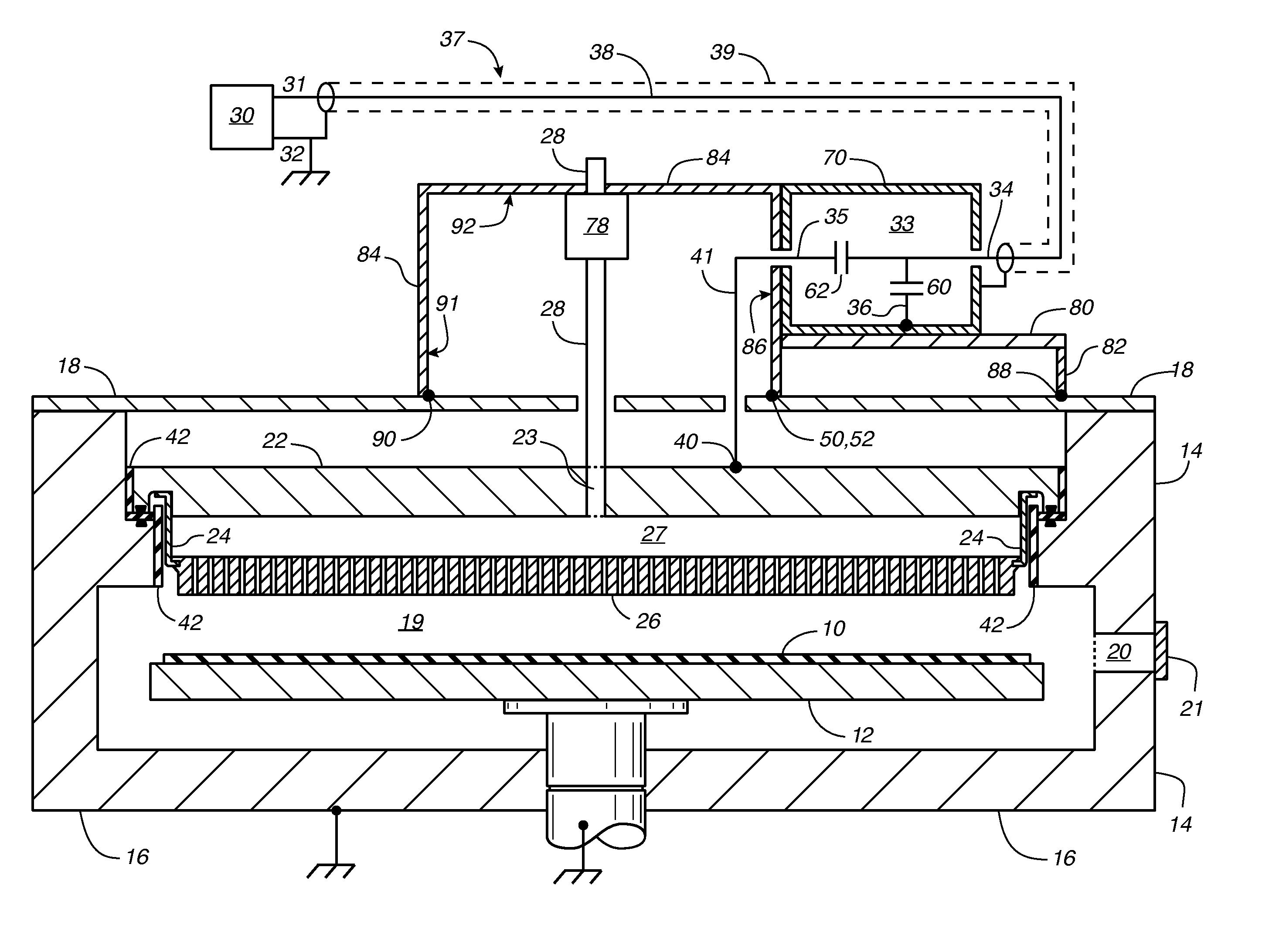
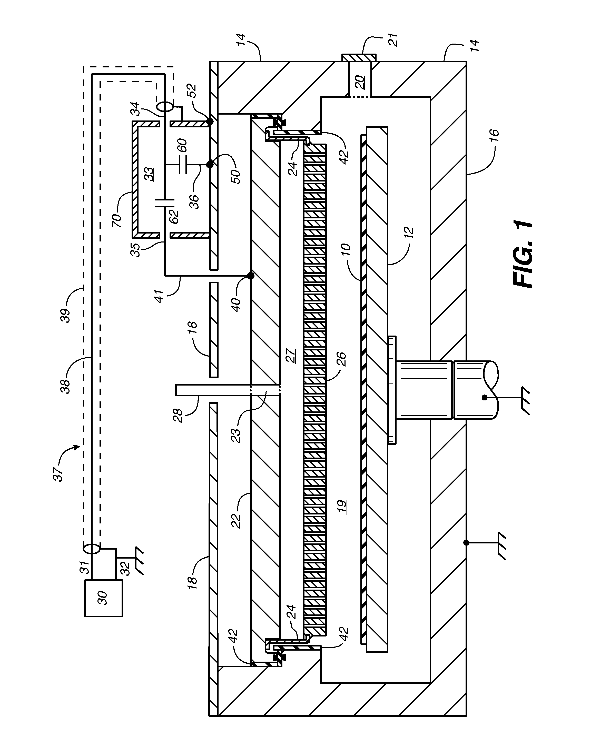
[0037]The present invention, according to a first aspect or first embodiment, compensates for the asymmetry caused by the workpiece passageway 20 by providing an offset ground connection between the RF impedance matching network 33 and the chamber cover 18. Advantageously, this enables an improvement in the spatial uniformity of a plasma process performed in the chamber.

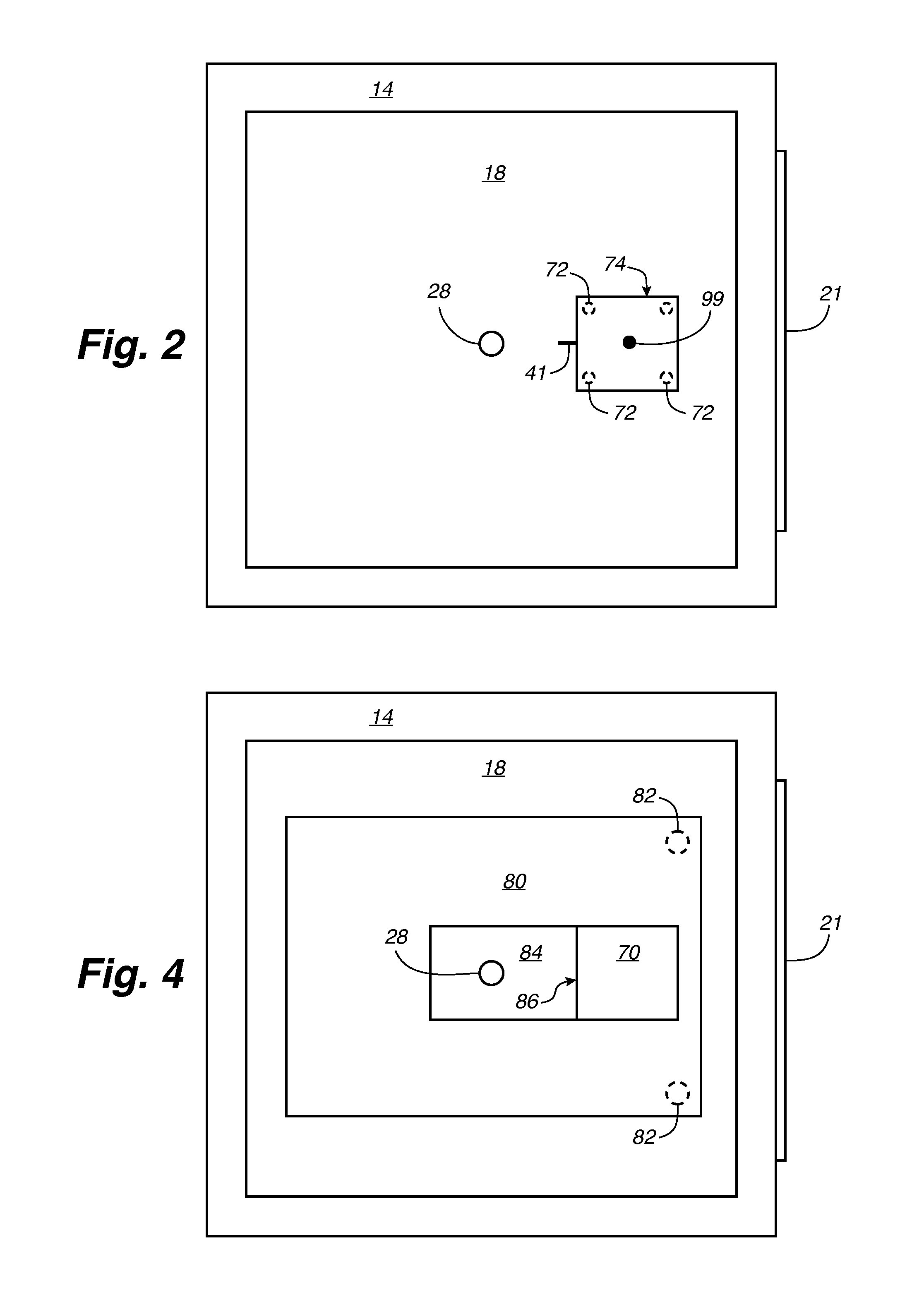
[0038]Specifically, the first aspect or first embodiment of the invention provides an electrical connection between an electrical ground 36 of the RF impedance matching network 33 and at least a first connection area 50 on the electrically grounded chamber cover 18 of the plasma chamber. The first connection area on the chamber cover is offset away from the center of the chamber cover toward the workpiece passageway 20.

[0039]We use the term “electrical ground 36 of the RF impedance matching network” to mean any portion of the RF impedance matching network 33 that is connected to electrical ground. In the embodiment s...

second embodiment

[0058]An electrical connection between the grounded conductor 39 of the RF transmission line 37 and one of the electrically grounded components of the plasma chamber can provide an RF ground return path to the RF power supply 30. A second aspect or second embodiment of the invention is to connect the grounded conductor 39 of the RF transmission line to a second connection area 52 on the chamber cover 18, wherein the second connection area is offset away from the center of the chamber cover toward the workpiece passageway.

[0059]Alternatively, if the output 31 of the RF power supply is connected directly to the input 34 of the impedance matching network without an intervening RF transmission line 37 (as would be possible if the RF power supply 30 is located adjacent the RF impedance matching network 33), then the second aspect or second embodiment of the invention can be defined as the RF power supply having a grounded output 32 that is electrically connected to a second connection ar...


PUM

PropertyMeasurementUnit
electrically conductiveaaaaaaaaaa
areaaaaaaaaaaa
perimeteraaaaaaaaaa

Abstract

An electrical ground (36) of an RF impedance matching network (33) is connected to a connection area (50) on the grounded chamber cover (18) of a plasma chamber. The connection area is offset away from the center of the chamber cover toward a workpiece passageway (20). Alternatively, an RF power supply (30) has an electrically grounded output (32) that is connected to a connection area (52) on the chamber cover having such offset. Alternatively, an RF transmission line (37) has an electrically grounded conductor (39) that is connected between a grounded output of an RF power supply and a connection area (52) on the chamber cover having such offset.

Description

CROSS-REFERENCE TO RELATED APPLICATIONS[0001]This patent application claims the benefit of U.S. Provisional Application No. 61 / 246,535 filed Sep. 29, 2009 and U.S. Provisional Application No. 61 / 252,672 filed Oct. 17, 2009.TECHNICAL FIELD[0002]The invention relates generally to methods and apparatus for coupling an RF power source to a showerhead electrode of a plasma chamber used for fabricating electronic devices such as semiconductors, displays and solar cells. The invention relates more specifically to improving the uniformity of a plasma process performed in the plasma chamber by providing an electrical ground connection between an electrically grounded cover of the plasma chamber and either an RF impedance matching network or an RF transmission line.BACKGROUND ART[0003]Plasma chambers commonly are used to perform processes for fabricating electronic devices such as semiconductors, displays and solar cells. Such plasma fabrication processes include chemical vapor deposition of ...

Claims


Application Information

Patent Timeline
Patent Type & Authority Patents(United States)
IPC IPC(8): H01J37/32
CPCH01J37/32174H01J37/32091H01J37/32577Y10T29/49117H01J37/32183H01J37/3244
Inventor BAEK, JONGHOONPARK, BEOM SOOKIM, SAM HYUNGSAM
Owner APPLIED MATERIALS INC
Why Eureka
Try Eureka