Electronic oscillation circuit

a technology of electronic oscillator and circuit, which is applied in the direction of logic circuits, generator stabilization, and automatic control of pulses, can solve the problems of difficult integration and circuit according disadvantages, and achieve the effect of large selectivity and good separation of a single signal

Active Publication Date: 2015-05-26
ANHARMONIC
View PDF11 Cites 1 Cited by
  • Summary
  • Abstract
  • Description
  • Claims
  • Application Information

AI Technical Summary

Benefits of technology

[0021]According to the present invention, this problem is solved by applying a down conversion oscillator. In the down conversion process the desired signal is mapped to another frequency, for instance a low IF or even DC, which maps other signals to different frequencies, thus creating a good separation. The down converter can be combined with a low pass filter or a second low speed IF to DC filter to give a large selectivity for a single signal.

Problems solved by technology

This solves the disadvantage of the circuits according to the art, that are difficult to integrate in a chip due to elements required such as temperature sensor next or close to the resonator, a varicap on or close to the resonator, or frequency selective elements (filters).

Method used


Image

  • Electronic oscillation circuit
  • Electronic oscillation circuit
  • Electronic oscillation circuit

Examples


Embodiment Construction

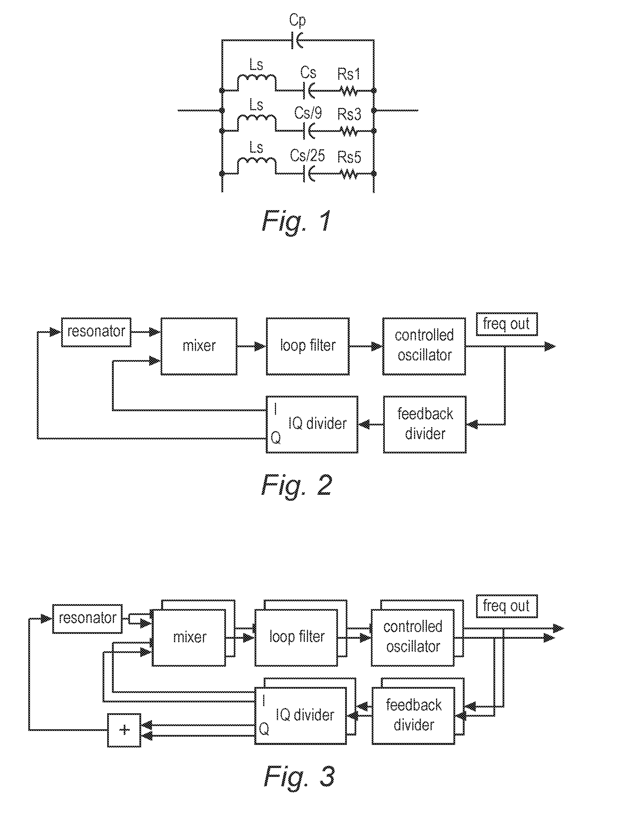
[0031]FIG. 1 shows a model of a resonator according to the art. The model comprises components for a single basetone, a single third overtone, single fifth overtone, and the parallel capacitance is present. This capacitance can be made part of the oscillation (parallel resonance) or not (series resonance). The overtones are harmonic overtones, which makes the model unsuitable for the present invention. In practice, the value of the capacity in series with Rs1≈Cs / 3, the value of the capacity in series with Rs3≈Cs / 9, etc.

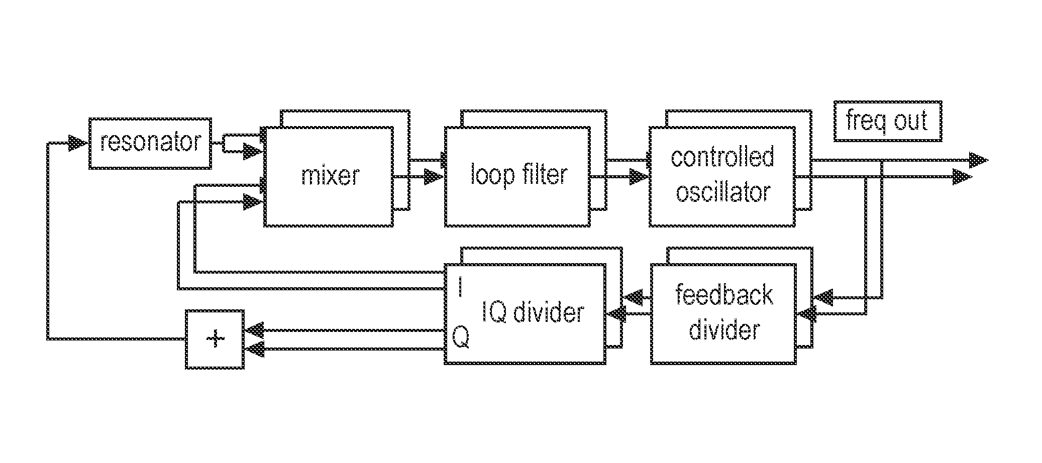
[0032]FIG. 2 shows a block diagram of a single mode oscillation circuit without temperature compensation, according to a patent application by the same applicant. In the figure, an example of a down conversion oscillator is shown. The basis is that the resonator shows a frequency dependent phase shift such that the feedback system searches for the correct phase alignment, at which the resonance has been ‘found’. The mixer requires for the steady state solution that th...


PUM


Abstract

An electronic oscillator circuit has a first oscillator, for supplying a first oscillation signal, a second oscillator, for supplying a second oscillation signal, a first controller for delivering the first control signal as a function of a phase difference between a first controller input and a second controller input of the first controller; a second controller for delivering the second control signal as a function of a phase difference between a first controller input of the second controller and a second controller input of the second controller; a resonator; at least a second resonance frequency, with a first phase shift dependent on the difference between the frequency of a second exciting signal and the second resonance frequency and processing means, for receiving the first oscillator signal and the second oscillator signal, determining their mutual proportion, looking up a frequency compensation factor in a prestored table and outputting a compensated oscillation signal.

Description

CROSS-REFERENCE TO RELATED APPLICATIONS[0001]This application is the United States national phase of International Application No. PCT / NL2012 / 050666 filed Sep. 20, 2012, and claims priority to Netherlands Patent Application No. 2007682 filed Oct. 31, 2011, the disclosures of which are hereby incorporated in their entirety by reference.BACKGROUND OF THE INVENTION[0002]1. Field of the Invention[0003]The present invention relates to an electronic oscillator circuit, and to a method for operating such a circuit. More in particular the invention relates to an electronic oscillator circuit with a reduced temperature sensitivity.[0004]2. Description of Related Art[0005]Electronic oscillator circuits generally comprise an element that causes an oscillation, or that can be brought in resonance, and then causes an oscillation. These oscillations can be used as a frequency or time reference in electronic circuits. The higher exactness that is required, the higher accuracy requirements are set ...

Claims


Application Information

Patent Timeline
Patent Type & Authority Patents(United States)
IPC IPC(8): H03B5/32H03B5/36H03B27/00H03L1/02H03L7/02
CPCH03L7/02H03B5/36H03B27/00H03L1/026
Inventor MONTAGNE, ANTONIUS JOHANNES MARIA
Owner ANHARMONIC
Why Eureka
Try Eureka