Image pickup apparatus and focus detection method

a pickup apparatus and focus detection technology, applied in the field of image pickup apparatus, can solve the problems of deteriorating the focus detection performance of a specific object such as a transverse line, requiring a long calculation time, and a narrow focus detection area to perform good focus detection, and achieve good accuracy

Inactive Publication Date: 2015-06-02
CANON KK
View PDF16 Cites 15 Cited by
  • Summary
  • Abstract
  • Description
  • Claims
  • Application Information

AI Technical Summary

Benefits of technology

[0010]The present invention provides an image pickup apparatus capable of performing focus detection in a focus detection area where pixels are two-dimensionally arranged, for various objects with good accuracy without requiring an excessively long calculation time.

Problems solved by technology

This is because a focus detection area including only one pixel line is too narrow to perform good focus detection.
However, the first one of the image signal producing methods disclosed in Japanese Patent Laid-Open No. 2010-152161 compresses the output of the two-dimensionally arranged pixels into a one-dimensional output, which deteriorates focus detection performance for a specific object such as a transverse line.
On the other hand, the second method disclosed therein requires calculation of an image displacement amount for each pixel line, which ensures a certain degree of focus detection performance, but requires a long calculation time.

Method used


Image

  • Image pickup apparatus and focus detection method
  • Image pickup apparatus and focus detection method
  • Image pickup apparatus and focus detection method

Examples


embodiment 1

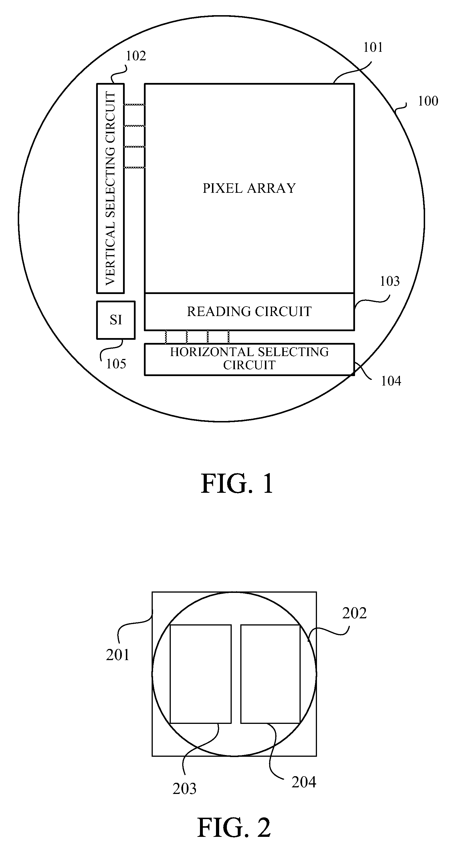
[0028]FIG. 1 shows a configuration of an image sensor (image pickup element) to be used in an image pickup apparatus that is a first embodiment (Embodiment 1) of the present invention. The image sensor 100 is provided with a matrix-like pixel array 101 constituted by plural pixels arranged in a horizontal direction that is a first direction and in a vertical direction that is a second direction orthogonal to the first direction.

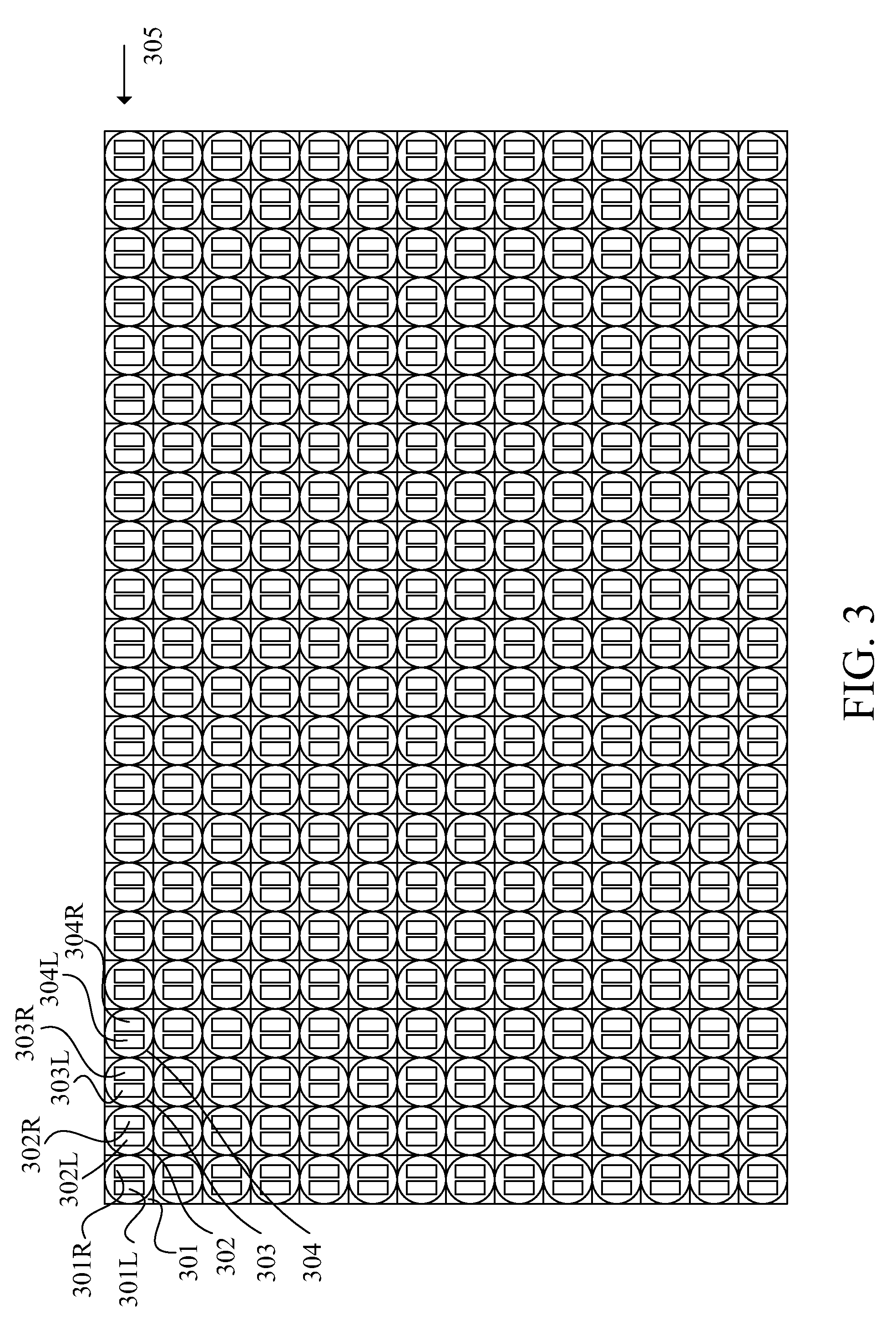
[0029]In the following description, a group of pixels lined in the horizontal direction is referred to as “a pixel line”, and a group of pixels lined in the vertical direction is referred to as “a pixel column”. The pixel array 101 includes plural pixel lines each of which includes plural pixels lined in the horizontal direction and which are arranged in the vertical direction. In other words, the pixel array 101 includes plural pixel columns each of which includes plural pixels lined in the vertical direction and which are arranged in the horizontal directio...

embodiment 2

[0063]Next, description of a second embodiment (Embodiment 2) of the present invention will be made with reference to FIGS. 9A and 9B. FIGS. 9A and 9B show that a substantial size of a focus detection area 603 to be decided depending on a focus detection area 602 including pixel lines p to q in an X (horizontal) direction and pixel columns r to s in a Y (vertical) direction and on a maximum shift amount Imax can be changed according to image capturing conditions.

[0064]The focus detection areas 602 and 603 shown in FIG. 9B are set to be narrower in the horizontal and vertical directions than the focus detection areas 602 and 603 shown in FIG. 9A. The change in sizes of the focus detection areas aims to respond to the fact that the image displacement amount of the A and B images or a size of the A and B images is changed depending on at least one of the image capturing conditions such as a focus state of an image capturing optical system and an F-number thereof.

[0065]For example, sinc...

embodiment 3

[0067]Next, description of a third embodiment (Embodiment 3) of the present invention will be made with reference to FIG. 10. Embodiment 2 has described the case where it is desirable that the change in size of the focus detection area be performed in the horizontal and vertical directions at image capturing of each still image and at image capturing of each frame of a moving image. However, in the vertical direction in which the pixel lines are arranged, the size of the focus detection area may be changed according to various image capturing conditions, without the image capturing (that is, during the image capturing of each still image and during the image capturing of each frame image).

[0068]FIG. 10 shows a state where a substantial focus detection area 603 set in the image sensor 100 is vertically divided into plural areas (each hereinafter referred to as “a divided area”) 1001, 1002 and 1003. Each of the divided areas 1001, 1002 and 1003 includes plural pixel lines and plural p...


PUM


Abstract

The image pickup apparatus includes an image sensor photoelectrically converting paired object images formed by light fluxes from mutually different pupil areas of an image capturing optical system, a signal producing part producing, by using output from each of plural pixel lines in a focus detection area in the image sensor, paired image signals corresponding to the paired object images for each pixel line, a calculating part calculating a defocus amount by using the paired image signals produced for each pixel line. The calculating part shifts the paired image signals relatively, produce first correlation data showing change of a correlation value of the paired image signals according to their relative shift amount, adds the first correlation data produced for the respective plural pixel lines to produce second correlation data, and calculates the defocus amount from the second correlation data.

Description

BACKGROUND OF THE INVENTION[0001]1. Field of the Invention[0002]The present invention relates to an image pickup apparatus that detects a focus state of an image capturing optical system by using output from an image sensor for photoelectrically converting an object image.[0003]2. Description of the Related Art[0004]Such an image pickup apparatus photoelectrically converts, by plural focus detecting pixels provided in the image sensor, paired object images formed by light fluxes passing through mutually different two areas (hereinafter referred to as “two pupil areas”) in an exit pupil of the image capturing optical system to produce paired image signals from the focus detecting pixels. The image pickup apparatus performs correlation calculation on the paired image signals to calculate a phase difference, which is a relative positional difference amount (image displacement amount), between the paired image signals, and then calculates a defocus amount corresponding to a focus state ...

Claims


Application Information

Patent Timeline
Patent Type & Authority Patents(United States)
IPC IPC(8): H04N5/232H04N5/228G02B7/34H01L27/146H04N5/369
CPCH01L27/14601G02B7/34H04N5/23212H04N5/3696H04N23/672H04N25/704
Inventor KISHI, TAKAFUMI
Owner CANON KK
Why Eureka
Try Eureka