
Lighting device monitor and communication apparatus

Active Publication Date: 2015-06-02
ALSI HLDG LLC
View PDF16 Cites 38 Cited by
  • Summary
  • Abstract
  • Description
  • Claims
  • Application Information

AI Technical Summary

Benefits of technology

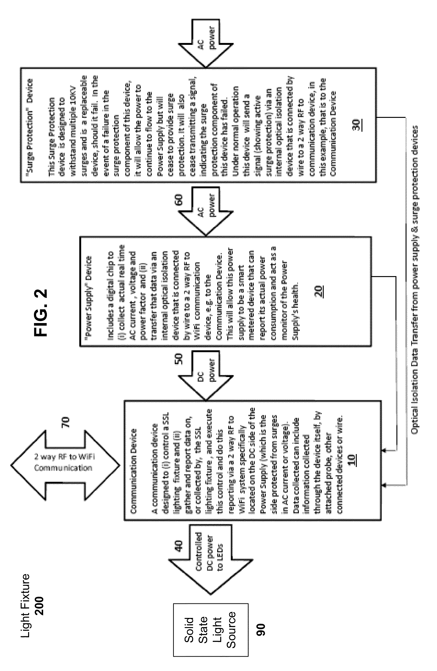
This patent describes a new system for remotely controlling lighting fixtures using RF and WiFi. The system measures and reports the voltage and wattage of the fixture, allowing for better control of its brightness. It also allows multiple remote systems to be meshed together. The system includes an AC power measurement device placed in the fixture's power supply, which sends real-time readings of current, voltage, and power factor through an optical isolation device to a communication device for wireless transmission to a remote device.

Problems solved by technology

Although hand held and other test equipment exist, such equipment is completely external to the electrical appliance and the power supply.
However, when such surge protection stops functioning, power in most cases (unless due to a catastrophic failure) continues to flow to the light fixture without any external evidence of failure and will no longer provide surge protection for the next incident of surge.

Method used


Image

  • Lighting device monitor and communication apparatus
  • Lighting device monitor and communication apparatus
  • Lighting device monitor and communication apparatus

Examples


Embodiment Construction

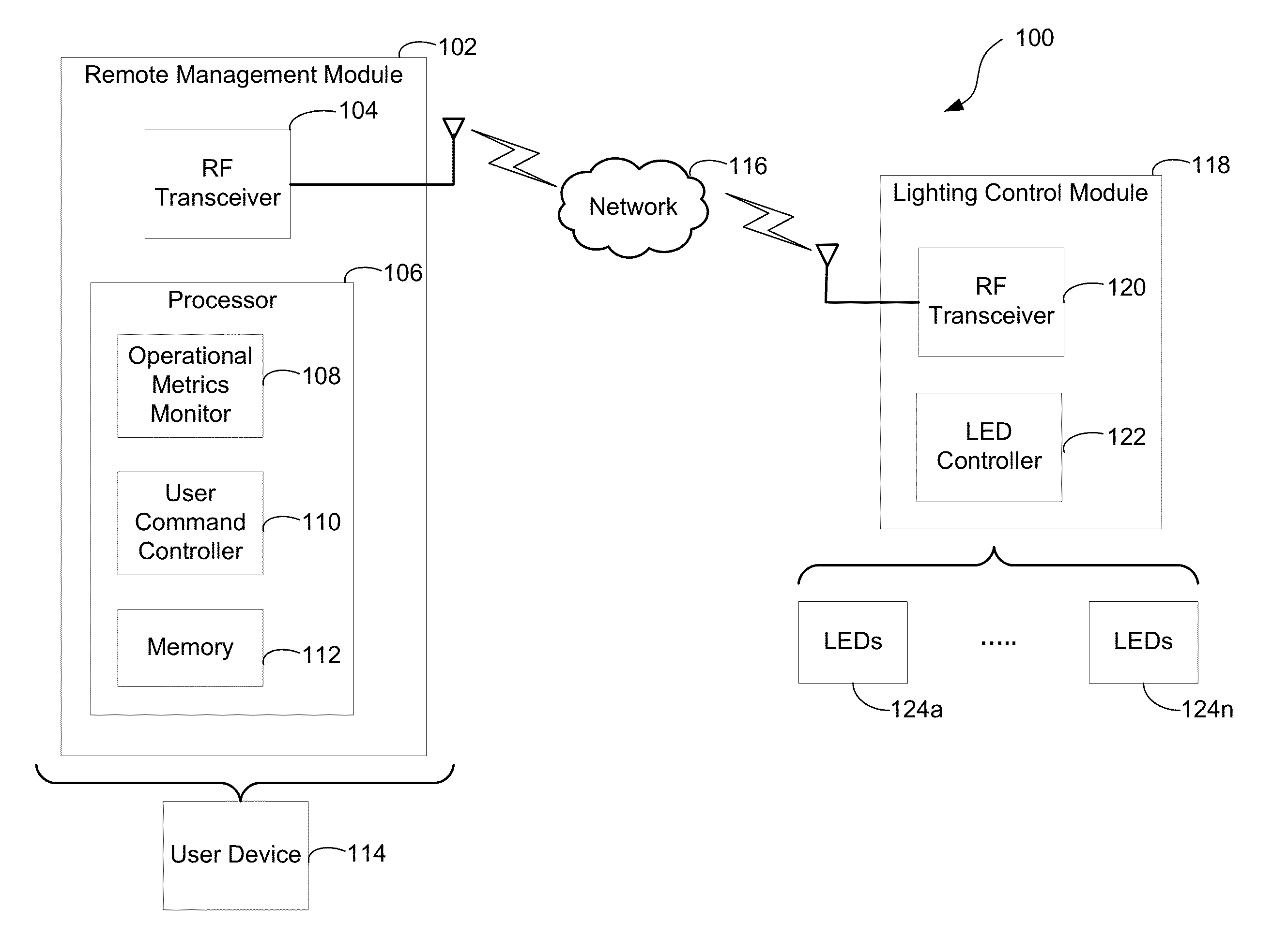
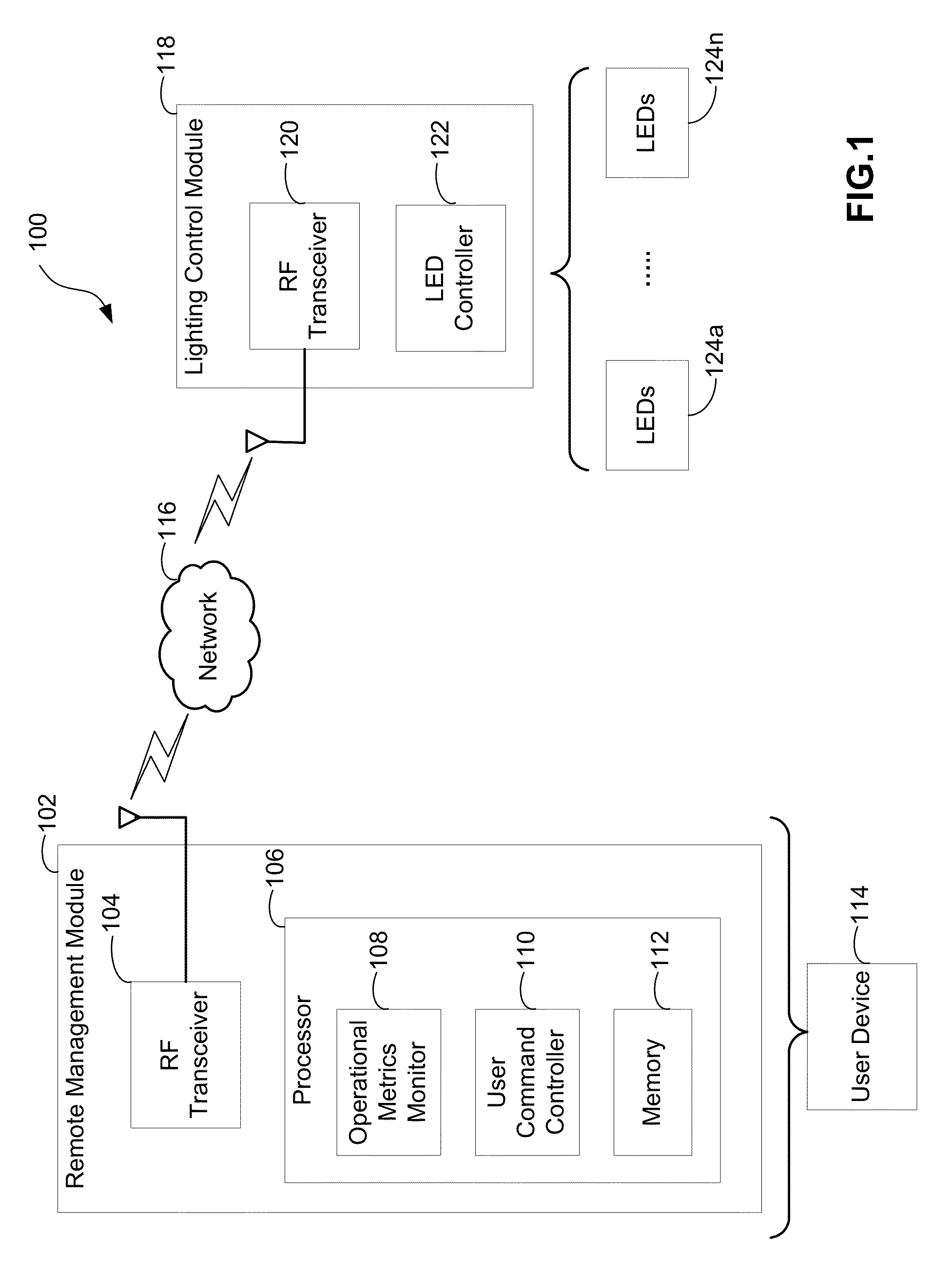
[0022]Referring to FIG. 1, a schematic system diagram 100 of an example remote control module 102 in communication with a wireless lighting module 118 via a network 116 in accordance with aspects of the present application. Remote control module 102 may include a computer circuit integrated with a microcontroller 106 driven RF transceiver module 104 for securely communicating with various wireless devices connected with the wireless network 116. In some examples, network 116 may be contemplated via various conventional and / or advanced wireless network techniques. In one aspect, a wireless mesh network (WMN) may advantageously offer a broadband wireless communication environment for areas where wired infrastructure is not available or not worthy to deploy. Due to WMN's inherent characteristics, such as self-configuring and self-healing capabilities, the WMN can be easily deployed and maintained. However, those of skill in the art will recognize that the devices and methods disclosed ...


PUM


Abstract

A smart metered light fixture including a light source. The light fixture includes a surge protection device with a monitor that indicates when surge protection fails. The light fixture includes a power supply monitor configured to collect real-time AC current, voltage, and power factor measurements from a power supply. An operational characteristic monitor monitors an operational characteristic of the light source, such as current consumption, wattage, real-time temperature, a brightness level, and / or an efficiency of the light fixture. A communication device positioned between the power supply receives information from the monitors and wirelessly transmits information regarding the monitored operational characteristic and information and / or power supply measurements to a remote user equipment. The communications device may also receive control instructions from the remote user equipment for controlling aspects of the light source.

Description

CLAIM OF PRIORITY UNDER 35 U.S.C. §119[0001]The present application for patent claims priority to Provisional Application No. 61 / 525,448 titled “Lighting Device Communication Apparatus” filed Aug. 19, 2011, and Provisional Application No. 61 / 542,556, titled Lighting Device Including Power Supply and Surge Protection Monitoring, filed Oct. 3, 2011, the entire contents of both of which are hereby expressly incorporated by reference herein.BACKGROUND[0002]1. Field of the Application[0003]Aspects relate, in general, to electronic power supplies, and specifically to lighting fixtures, e.g., luminaires, that utilize light emitting diodes (LEDs) as a light source and, more particularly, to lighting fixtures incorporating LEDs configured in a manner to amplify and direct light produced by such lighting fixtures. Aspects further include smart monitoring and remote control of such lighting fixtures.[0004]2. Background of the Technology[0005]It is desirable to adjust the amount of light genera...

Claims


Application Information

Patent Timeline
IPC IPC(8): H05B37/02H05B41/36H05B39/04H05B44/00
CPCH05B37/02H05B47/19Y02B20/40H05B47/10H05B45/14
Inventor WASSEL, JAMES J.RONEY, JOHN R.
Owner ALSI HLDG LLC
Learn More