Compressed air supply system, compressed air supply device for vehicle, and method of controlling air compressor

a compressed air supply and air compressor technology, applied in the direction of braking systems, separation processes, braking components, etc., can solve problems such as difficulty in recovering adsorption performan

Active Publication Date: 2015-06-09
NABTESCO AUTOMOTIVE CORP
View PDF63 Cites 6 Cited by
  • Summary
  • Abstract
  • Description
  • Claims
  • Application Information

AI Technical Summary

Benefits of technology

[0015]Under the circumstances, a first objective of a preferred embodiment of the present invention is to improve the performance of the vehicle by controlling an influence of the operation of the air compressor on the engine performance.
[0017]Under the circumstances, a second objective of a preferred embodiment of the present invention is to accurately determine the replacement time for the drying agent for removing the moisture in the compressed air discharged from the air compressor.
[0021]Under the circumstances, a fourth objective of a preferred embodiment of the present invention is to prevent the moisture accumulated in the air dryer from being frozen, and to save the consumption of the compressed air required for exhausting the moisture.
[0024]Under the circumstances, a fifth objective of a preferred embodiment of the present invention is to accurately determine the replacement time for the drying agent for removing the moisture in the compressed air discharged from the air compressor regardless of the installation position of the humidity detection sensor.
[0049]According to a preferred embodiment of the present invention, when there is a need to brake the vehicle, the air compressor driven by the engine of the vehicle is put into the load state to exert the load on the engine with the result that the braking force of the engine brake as the auxiliary braking device can be increased.
[0052]Further, according to a preferred embodiment of the present invention, the consumption of the compressed air, which is caused by exhaust of the moisture, can be suppressed while the freezing of the moisture in the air dryer is surely prevented.

Problems solved by technology

Incidentally, most of the air compressors mounted in the vehicles are driven by engines, and become loads on the engines.
Further, in the above conventional device, when the deterioration of the absorption agent is advanced with the continuous use, there is a difficulty to recover the adsorption performance even if the regeneration is conducted as described above.

Method used


Image

  • Compressed air supply system, compressed air supply device for vehicle, and method of controlling air compressor
  • Compressed air supply system, compressed air supply device for vehicle, and method of controlling air compressor
  • Compressed air supply system, compressed air supply device for vehicle, and method of controlling air compressor

Examples


first preferred embodiment

[0079]Hereinafter, a preferred embodiment of the present invention will be described with reference to the drawings.

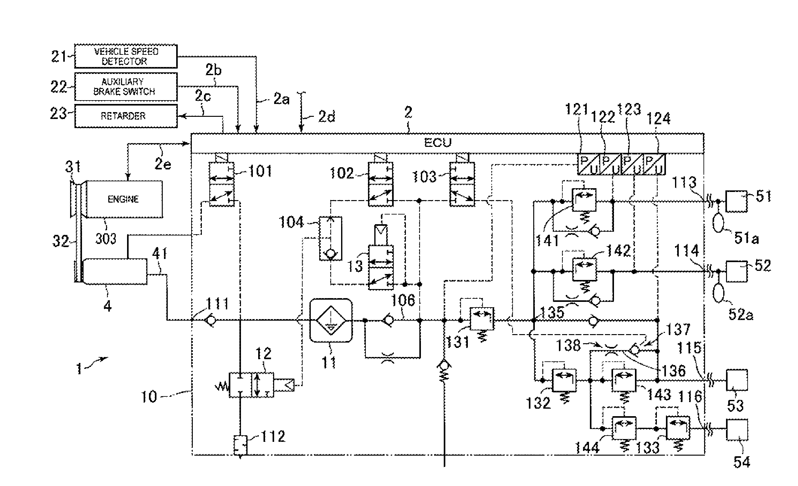
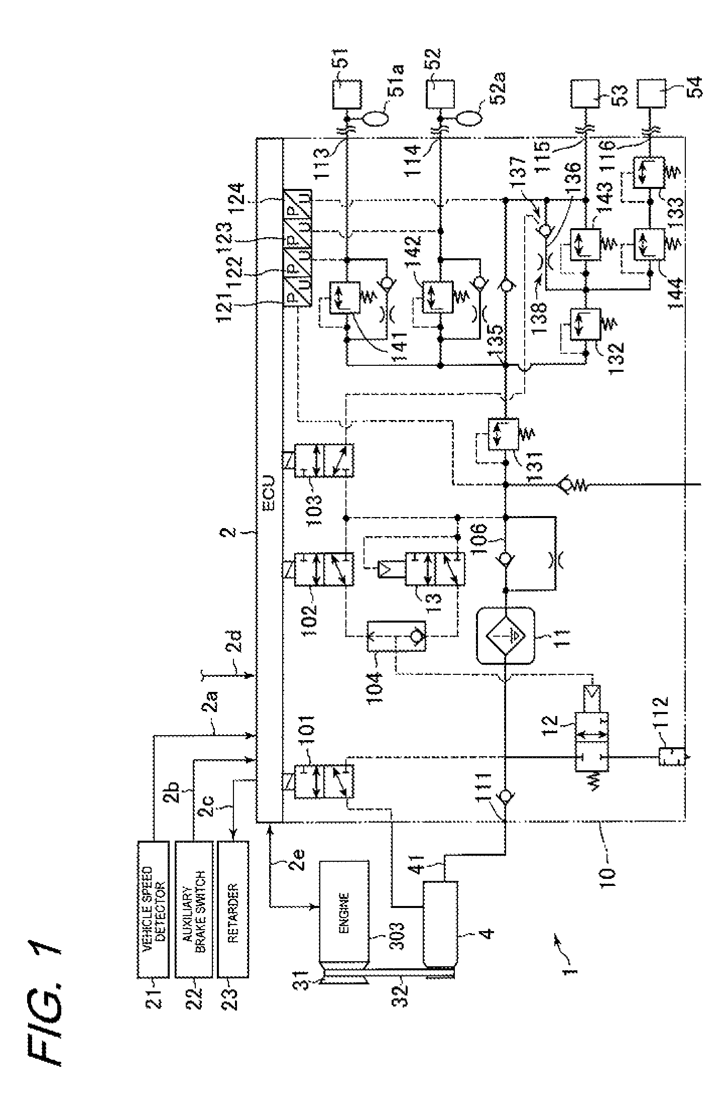
[0080]FIG. 1 is a diagram illustrating a configuration of a compressed air supply system 1 according to a preferred embodiment of the present invention. FIG. 1 illustrates a circuit configuration of the compressed air supply system 1 together with an engine 303 of a vehicle in which the compressed air supply system 1 is mounted, a vehicle speed detector 21, an auxiliary brake switch 22, and a retarder 23.

[0081]The compressed air supply system 1 illustrated in FIG. 1 includes a compressor 4 (air compressor), an ECU 2 (controller) that controls the compressor 4, and an air dryer module 10 (compressed air supply unit) that removes moisture in a compressed air discharged from the compressor 4, and supplies the compressed air to a load of the vehicle.

[0082]The ECU 2 is connected with the vehicle speed detector 21 that detects a speed of the vehicle in which the compressed a...

second preferred embodiment

[0147]FIG. 6 is a diagram illustrating a configuration of a compressed air supply system 1 according to a second preferred embodiment of the present invention.

[0148]In the second preferred embodiment, the respective parts identical with those in the first preferred embodiment are denoted by the same references, and their description will be omitted.

[0149]The compressed air supply system 1 (compressed air supply device for a vehicle) illustrated in FIG. 6 includes a compressor 4 (air compressor), an ECU 2 that controls the compressor 4, and an air dryer module 10 that removes moisture in a compressed air discharged from the compressor 4, and supplies the compressed air to a load of the vehicle.

[0150]The ECU 2 controls an engine of the vehicle and also controls the operation of the compressor 4 and the air dryer module 10, on the basis of the speed of the vehicle in which the compressed air supply system 1 is mounted.

[0151]The air dryer module 10 is connected with loads 51 to 54 provi...

third preferred embodiment

[0183]FIG. 8 is a diagram illustrating a configuration of a compressed air supply system 1 according to a third preferred embodiment.

[0184]In the third preferred embodiment, the respective parts identical with those in the second preferred embodiment are denoted by the same references, and their description will be omitted.

[0185]In the compressed air supply system 1 of the third preferred embodiment, unlike the above-mentioned second preferred embodiment, the oil detection sensor 14 is disposed in a pipe for the compressed air, which is connected to a downstream side of the air dryer 11.

[0186]That is, the oil detection sensor 14 is located outside the case 20 of the air dryer 11, and detects the amount of oil mist in the compressed air that has passed through the drying agent 231 within the case 20. The oil detection sensor 14 is configured by, for example, an oil mist sensor 141 described in the second preferred embodiment, which is connected to the ECU 2, measures the concentratio...


PUM


Abstract

The operation of an air compressor is controlled to control engine performance to thereby improve the performance of the vehicle. A compressor (4) driven by an engine (3) of a vehicle and supplying compressed air to loads (51-54) is controlled by an ECU (2). A loaded state and an unloaded state of the compressor (4) are switched between each other according to the requirements from the loads (51-54). When the vehicle requires braking force, the compressor (4) is set to the loaded state irrespective of the requirements from the loads (51-54).

Description

CROSS-REFERENCE TO RELATED APPLICATIONS[0001]This application is a Section 371 of International Application No. PCT / JP2010 / 052795, filed Feb. 23, 2010, which was published in the Japanese language on Aug. 26, 2010, under International Publication No. WO 2010 / 095754 A1 and the disclosure of which is incorporated herein by reference.BACKGROUND OF THE INVENTION[0002]The present invention relates generally to a compressed air supply system, a compressed air supply device for a vehicle, and a method of controlling an air compressor, which supplies a compressed air by the air compressor mounted in the vehicle.[0003]Up to now, a device has been known in which when a compressed air discharged from an air compressor for a vehicle is accumulated in an air tank, and supplied to a load of the vehicle, in order to prevent the shortage of pressure in the air tank, the air compressor is switched to a load state according to a status of the vehicle or the course (for example, refer to Patent Litera...

Claims


Application Information

Patent Timeline
Patent Type & Authority Patents(United States)
IPC IPC(8): B60T15/00B60T13/66B60T17/00B60T13/68B60T17/02
CPCB60T17/004B60T13/662B60T13/683B60T17/02B01D53/0454B01D2259/4566B01D2259/40083B01D2257/80
Inventor MINATO, ICHIROHASEBE, HIROKI
Owner NABTESCO AUTOMOTIVE CORP
Why Eureka
Try Eureka