Flashlight

a flashlight and flashing technology, applied in the field of flashing lights, can solve the problems of relatively high power consumption, relatively short service life, and relatively expensive fabrication mode, and achieve the effects of reducing manufacturing costs, facilitating fabrication, and simplifying construction

Inactive Publication Date: 2015-06-16
ZWEIBRUDER OPTOELECTRONICS BGMH & CO KG
View PDF21 Cites 14 Cited by
  • Summary
  • Abstract
  • Description
  • Claims
  • Application Information

AI Technical Summary

Benefits of technology

[0006]Another object is the provision of such an improved flashlight that overcomes the above-given disadvantages, in particular that is of simple constructive design and can be easily manufactured.SUMMARY OF THE INVENTION
[0008]Thus the LED is mounted without any solder joints in a holder so as to avoid unintentional relative movements of the diode relative to any electrical contacts, which motions in prior-art flashlights result in breakages of the lead wires. The holder not only serves to hold the diode but also is a reflector.
[0009]The holder furthermore has holes into which the lead wires can be easily inserted and then retained such that the connections to the battery are created in a solder-free fashion or are arranged such that a connection is made to close the electrical circuit containing the diode by appropriately actuating a switch. The lead wires are thus completely protected externally by the one-piece holder, thereby effectively preventing any accidental breaking of the lead wires since these lead wires are otherwise protected from possible compressive, pulling, or shearing motions.
[0010]In a first embodiment of the invention, for example, the flashlight head is rotatable relative to the flashlight casing and thus acts as a rotary switch. In one specific embodiment here, one of the lead wires can extend through the base of the one-piece holder and bent over there so that the wire rests permanently on the positive battery pole of the inserted battery or of the inserted battery pack. The second lead wire extends radially outward through a separate hole where it rests on a front face of the inside side surface of the battery compartment casing, where, depending on the rotational position, the lead wire rests on an insulated point or on an electrically conductive point that is in contact with the negative battery pole. This type of rotary head in the form of a switch is also less prone to wear than pressure-operated switches.
[0012]In order to simplify the construction and facilitate fabrication, another embodiment of the invention provides that the holder can be one piece and provided with an external thread that in the assembled state engages a correspondingly designed internal thread of the flashlight head. In another embodiment of the invention, this internal thread of the flashlight head can also be designed to correspond to the external thread of the flashlight casing, with the result that the internal thread of the flashlight head engages both the external thread of the holder as well as the external thread of the flashlight casing.
[0013]In a special embodiment of the invention, the holder can also be composed of an injection-molded plastic part, thereby considerably reducing the cost of manufacture. If translucent plastic is selected as the material for the holder, which additionally includes an annular projection, it is possible to create a shape in which this ring is disposed between the flashlight head and the flashlight casing, the ring preferably fitting flush with the side surface of the flashlight head and the flashlight casing. When the flashlight is switched on, this ring acts an illuminated annular surface that can also be utilized as a support surface for information in another embodiment of the invention. This information can be engraved into the annular surface, in particular by a laser so as to contain technical information or information from the manufacturer, also for advertising purposes.

Problems solved by technology

The disadvantage of incandescent bulbs is their relatively short service life as well as their relatively high power consumption, and for this reason LEDs are widely used as the light source.
The disadvantage of this arrangement consists in the relatively costly mode of fabrication and the fabrication defects that cannot be avoided in the soldering process.

Method used


Image

  • Flashlight
  • Flashlight
  • Flashlight

Examples


Embodiment Construction

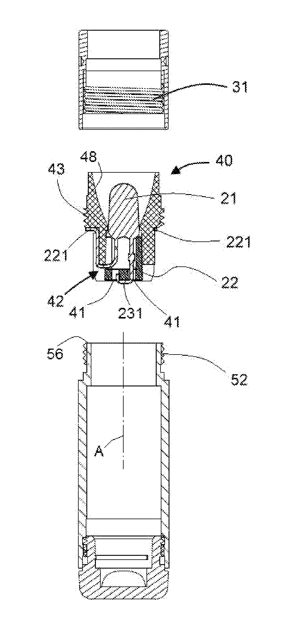
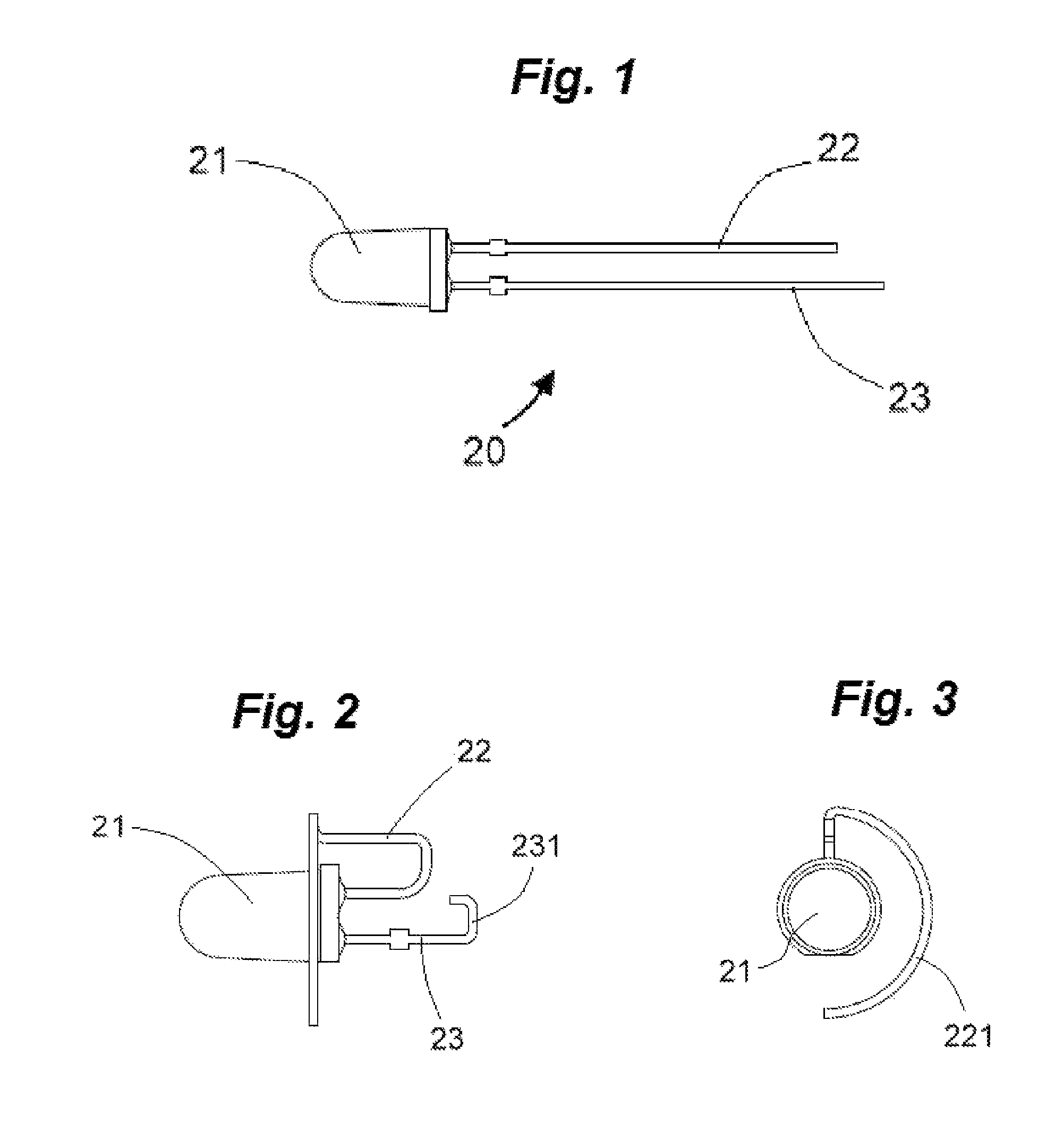
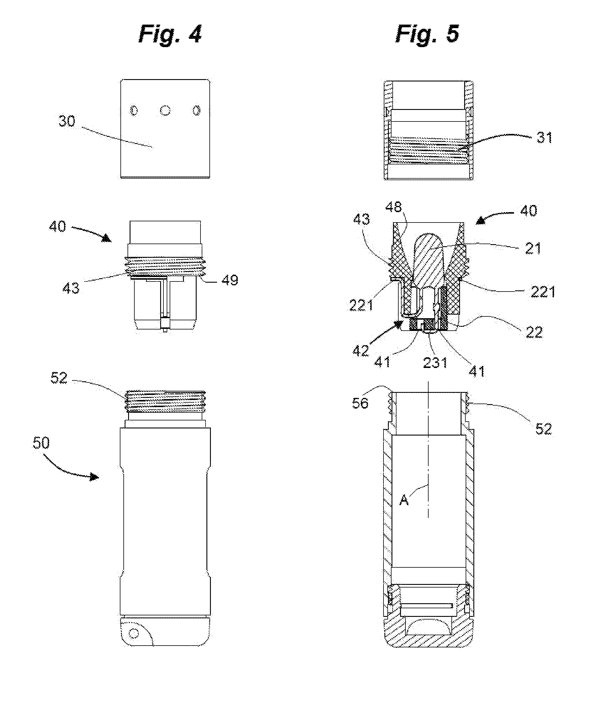
[0027]As seen in FIG. 1, a standard LED 20 has a light-emitting head 21 and integral two lead wires 22 and 23 projecting from the bottom of the head 21. These wires 22 and 23 have the shape seen in FIGS. 2 and 3 after being installed as described below in a holder with the appropriate bending and insertion through holes in the holder. At is bottom end, lead wire 23 is bent like a hook with its outer end 231 in a U-shape so as to form a contact line or contact surface with a positive battery pole of a battery or of the top-most battery of a battery stack. The lead wire 22 is bent radially outward and then bent upward and around to a partially ring-shaped or arcuate end 221 that, for example, rests as described below on the conductive end face of a battery casing, and connects through the casing wall to the negative battery pole.

[0028]In the exploded views of FIGS. 4 and 5, the flashlight is composed of a flashlight head 30 formed as a cylindrical collar, a one-piece holder 40, as wel...


PUM


Abstract

A flashlight has a casing extending along an axis, formed with a screwthread, and holding a battery having two poles. A light-emitting diode has a light-emitting head and a first and second integral lead wires. A holder is formed with first and second separate throughgoing holes, a seat into which the holes open and in which the diode head is fitted with the first and second wires extending outward through the respective first and second holes out of contact with each other, a reflector adjacent the seat, and a screwthread. The holder is fitted to the casing with the screwthread of the holder operatively engaged with the screwthread of the casing and the first wire pressed directly against one of the poles of the battery.

Description

FIELD OF THE INVENTION[0001]The present invention relates to a flashlight. More particularly this invention concerns a flashlight using a light-emitting diode (LED) as a light source.BACKGROUND OF THE INVENTION[0002]For decades flashlights have been among the indispensable tools for illuminating unlit paths, spaces, including small cavities or sign boards. Conventional flashlights are usually equipped with so-called incandescent bulbs that are screwed into a socket that in turn was one component of an electrical circuit actuatable by a switch. The incandescent bulb was located at the focal point of a concave reflector to focus its light and to ensure the optimal output of light. A relatively large and usually heavy battery functioned as the power supply point and was held in a battery compartment that simultaneously formed the handle of the flashlight.[0003]The disadvantage of incandescent bulbs is their relatively short service life as well as their relatively high power consumptio...

Claims


Application Information

Patent Timeline
Patent Type & Authority Patents(United States)
IPC IPC(8): F21V19/00F21L4/00F21V7/00F21V23/04F21L4/02F21Y101/02
CPCF21V19/0005F21L4/005F21L4/027F21V7/0075F21V19/006F21V23/0428F21Y2101/02F21Y2115/10
Inventor OPOLKA, RAINER
Owner ZWEIBRUDER OPTOELECTRONICS BGMH & CO KG
Why Eureka
Try Eureka