Optical fiber connector and an assembly method for the same

a technology of optical fiber connector and assembly method, which is applied in the direction of optical elements, manufacturing tools, instruments, etc., can solve the problems of short circuit problem, signal transmission loss might fast increase, and the optical fiber is disconnected, so as to prevent the damage of the ferrule, prevent the transformation of the ferrule, and improve the quality of the optical fiber

Active Publication Date: 2015-06-16
ILSIN OTS
View PDF34 Cites 6 Cited by
  • Summary
  • Abstract
  • Description
  • Claims
  • Application Information

AI Technical Summary

Benefits of technology

[0037]The optical fiber according to the present invention makes it possible to prevent a transformation of a ferrule by means of heat in such a manner that heat transferred to ferrule when heating a reinforcing sleeve is interrupted by a guide ferrule bush installed between a ferrule and an elastic member in such a manner that a ferrule and an elastic member do not contact with each other, so a hot peeling performed after heating is possible, thus preventing the damages of a ferrule which occurs due to a cold peeling.
[0038]In the conventional art, a ferrule optical fiber is peeled and then supplied in order to prevent a breaking of a boned portion between a ferrule body and a ferrule optical fiber occurring due to a cold peeling or a short circuit of a ferrule optical fiber, but when a peeled ferrule optical fiber is provided, it is exposed to the air for a long time, so the quality of the optical fiber changes, and it is hard to prevent the damages of a peeled optical fiber in the course of storage and movement. In the present invention, a hot peeling can be possible with the aid of a guide ferrule bush belonging to an optical fiber connector, so it does not need to supply a peeled ferrule optical fiber.
[0039]In addition, the guide ferrule bush is integrally formed with a reinforcing sleeve along with a ferrule bush, so it moves within a movement range of an elastic member, thus preventing a problem that a ferrule optical fiber is bent or becomes short circuit.
[0040]In the present invention, the reinforcing sleeve is formed of a thermal contraction tube with a thermal bonding layer in the interior in a single tube structure, so the storage and movement are easy, and the use of the same is convenient, and workability can be enhanced.

Problems solved by technology

At this time, a bending phenomenon occurs at a part 1b′ of the shorter ferrule optical fiber 1b, so the optical fiber is disconnected, and short circuit problem occurs.
Since a sharp angle bending occurs, a signal transmission loss might fast increase.
In this case, a bonded portion becomes weak due to the weight occurring during peeling, so a transformation or short circuit problem occurs.
In addition, when the ferrule is peeled off from an optical fiber at a factory and an adhesive is bonded, and a necessary cutting is performed and supplied to a construction site, a manufacture cost increases due to a hard work, and a short circuit problem might occur when doing such works at the construction site.
The peeled optical fiber might be exposed to the air for a long time, so it might be contaminated by moisture or optical pollutant materials.
In case that the optical fiber is supplied in a packed state, the manufacture cost increases, and since the entire volume of the products increase, which results in increasing transportation cost.

Method used


Image

  • Optical fiber connector and an assembly method for the same
  • Optical fiber connector and an assembly method for the same
  • Optical fiber connector and an assembly method for the same

Examples


Embodiment Construction

[0062]The preferred embodiments of the present invention will be described with reference to the accompanying drawings. The terms and words used in the descriptions and the claims are not intended to be interpreted as a conventional or limited meaning, and such terms and words should be preferably interpreted as having meaning and concepts matching with the technical concepts of the present invention based on the principles that the concepts of the words can be defined in a proper manner for the inventor to describe his own invention in the best mode.

[0063]Therefore, the embodiments and constructions of the descriptions of the present invention are for only illustrative purposes, not representing the technical concepts of the present invention, so it is obvious that there might be diverse equivalents and modifications which can substitute the inventions at the time of the application.

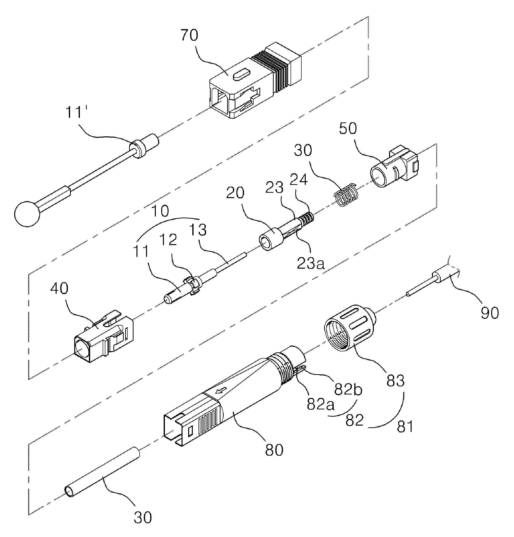
[0064]As shown in FIGS. 3 to 5, the optical fiber connector C according to the present invention com...


PUM

PropertyMeasurementUnit
thermal contractionaaaaaaaaaa
diameteraaaaaaaaaa
adhesionaaaaaaaaaa

Abstract

The present invention relates to an optical fiber connector whereby an operator can easily couple optical fibers on site, and to an assembly method for the same. More specifically the invention relates to: an optical fiber connector wherein a guide ferrule bush is provided between a ferrule and a coil spring so as to be able to solve a problem whereby a ferrule optical fiber between a ferrule body and a reinforcing sleeve is bent, and a problem whereby contact between the ferrule body and the ferrule optical fiber is broken due to frequent movement, when the ferrule moves within a range of movement provided for by a resilient member due to the resilient member; and to an assembly method for the same.

Description

RELATED APPLICATIONS[0001]This application is a 371 application of International Application No. PCT / KR2010 / 005713, filed Aug. 25, 2010, which in turn claims priority from Korean Patent Application No. 10-2010-0065973, filed Jul. 8, 2010, each of which is incorporated herein by reference in its entirety.TECHNICAL FIELD[0002]The present invention relates to an optical fiber connector and a method for assembling the same, and in particular to an optical fiber connector and a method for assembling the same which are directed to installing a guide ferrule bush between a ferrule and a coil spring in an attempt to overcome the problems that an adhesion state of an adhesion part between a ferrule body and a ferrule optical fiber or a ferrule expander and a ferrule optical fiber due to a frequent movement when a ferrule moves within a permitted (given) range due to a ferrule elastic member is broken or a ferrule optical fiber between a ferrule body and a reinforcing sleeve is bent.BACKGROUN...

Claims


Application Information

Patent Timeline
Patent Type & Authority Patents(United States)
IPC IPC(8): G02B6/38
CPCG02B6/3846G02B6/3823Y10T29/49826G02B6/3821G02B6/3893G02B6/2551G02B6/3801
Inventor PARK, CHAN SOULLEE, KWANG CHEONJUN, SANG CHULPARK, JUN YOUNG
Owner ILSIN OTS
Why Eureka
Try Eureka