Forming tool

a technology of forming tools and forming parts, which is applied in the field of forming tools, can solve the problems of inability to control the temperature regulation during the injection molding process, inconvenient to use such a conception of forming tools, and the method described in this document cannot be used with determined tool geometries, etc., and achieves hardly reduced free traversable cross-section

Inactive Publication Date: 2015-06-23
ROCTOOL SAS
View PDF16 Cites 5 Cited by
  • Summary
  • Abstract
  • Description
  • Claims
  • Application Information

AI Technical Summary

Benefits of technology

[0013]It is clear from the conformation of thus-designed inductors that the free traversable cross-section is hardly reduced by temperature regulation canals in a forming tool so that forming tools can be improved by providing their temperature regulation canals with such an inductor in an appropriate manner.

Problems solved by technology

A control of the temperature regulation during the injection moulding process is not possible with this design.
The inconvenient of such a conception of a forming tool is however its relative inertial behaviour.
Moreover, the method described in this document can only be used with determined tool geometries.

Method used


Image

  • Forming tool
  • Forming tool

Examples


Embodiment Construction

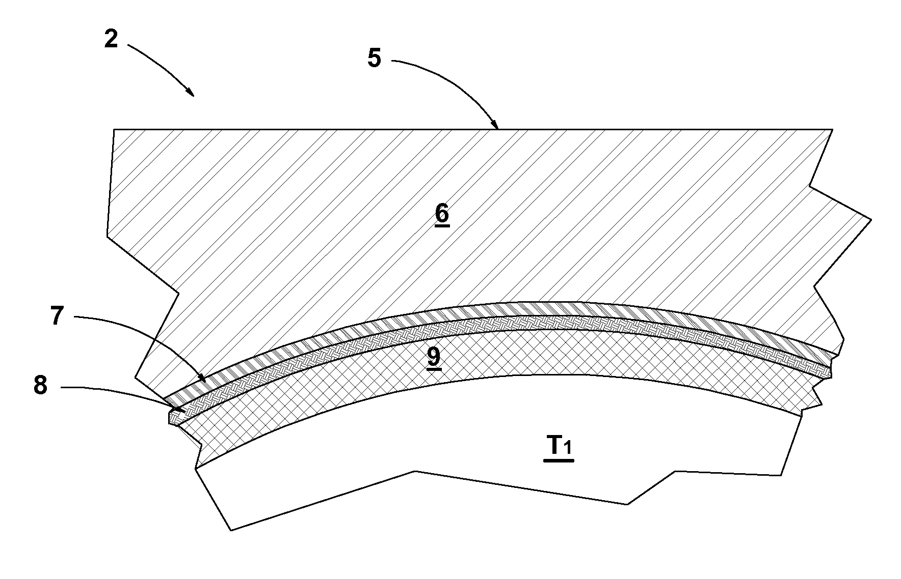
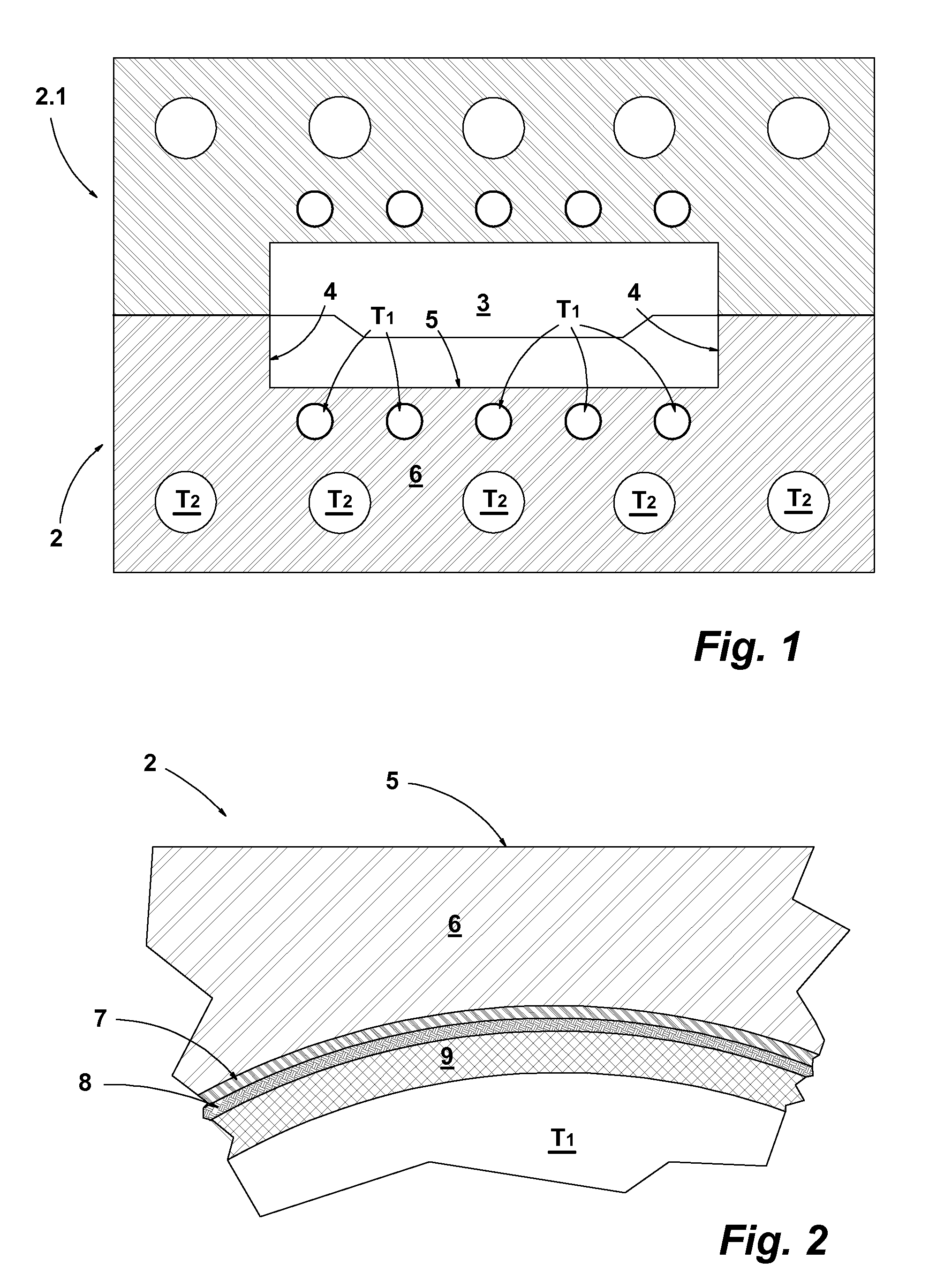
[0018]An injection mould 1 of a plastic material injection moulding tool, not represented otherwise in details, comprises in the represented embodiment example two forming tools 2, 2.1, which injection mould is represented in FIG. 1 in its closed position. A cavity 3, in which a plasticized plastic material is introduced through injection canals, not represented in details, is formed by both forming tools 2, 2.1. For simplicity reasons, the cavity 3 of the embodiment example in the sectional representation is designed with a rectangular shape. It must be understood that the geometry of the cavity 3 can finally have any shape and that, if the cavity has a complex geometry, more than two forming tools is necessary. The forming tools 2, 2.1 have basically the same design. The forming tool 2 is described in details subsequently.

[0019]The forming tool 2 is made from tool steel. The cavity limiting surface potions of the mould 2 are contact surfaces on which the fused plastic material int...


PUM

PropertyMeasurementUnit
thicknessaaaaaaaaaa
thicknessaaaaaaaaaa
diameteraaaaaaaaaa

Abstract

A forming tool, advantageously made from a metal with a forming contact surface (4, 5) and with one or several temperature regulation canals (T1) which are integrated in the tool (2, 2.1) and through which a fluid flows, characterized in that an electric conductor in the form of an inductor (9) is arranged at the internal wall of the temperature regulation canals (T1) and, if need be, with the insertion of a dielectric layer covering the temperature regulation canals (T1).

Description

BACKGROUND OF THE INVENTION[0001]1. Field of the Invention[0002]The invention relates to a forming tool, advantageously made from a metal with a forming contact surface and with one or several canals which are integrated in the tool and through which a fluid flows.[0003]2. Description of the Related Art[0004]When parts are moulded by injection from thermoplastic, duroplastic or elastomeric materials, the material, which has been plasticized beforehand, is introduced into the cavity of a mould. For making up the cavity, such a mould is composed of several forming tools which are separated from each other in order to remove the part cooled in the cavity. The surfaces of the forming tools, which are in contact with the moulding plastic material, are called contact surfaces within the context of these realisations. The image of these contact surfaces defines the surface of the part. The moulding precision of the part surface can be spoiled by defaults, for example by glued joint grooves...

Claims


Application Information

Patent Timeline
Patent Type & Authority Patents(United States)
IPC IPC(8): B29C33/06B29C45/73B29C35/08
CPCB29C33/06B29C45/7312B29C2035/0811
Inventor HINZPETER, UDO
Owner ROCTOOL SAS
Why Eureka
Try Eureka