

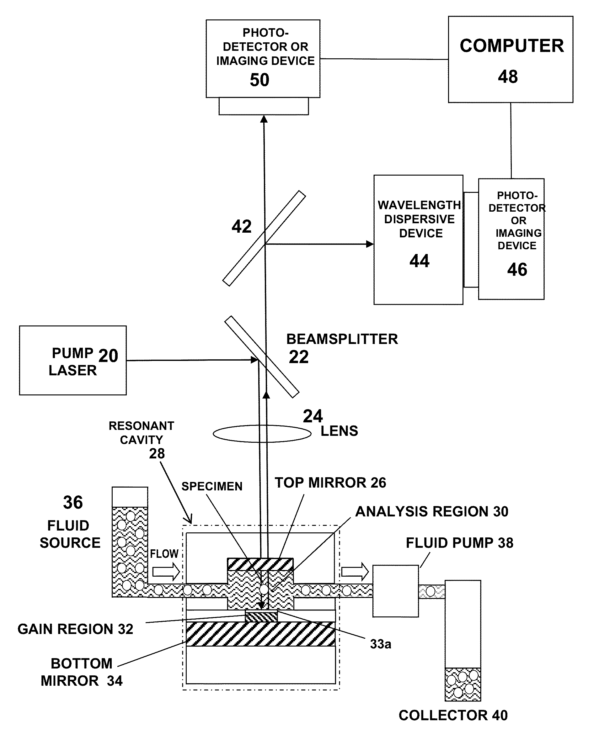
Micro-optical cavity with fluidic transport chip for bioparticle analysis
a micro-optical cavity and bioparticle technology, applied in material analysis, instruments, measurement devices, etc., can solve the problems of false readings and pathologists currently relying on labor-intensive microscopic examination, and achieve rapid, accurate analysis of optical properties, and calibration and maintenance of measurement fidelity during operation.
- Summary
- Abstract
- Description
- Claims
- Application Information
AI Technical Summary
Benefits of technology
Problems solved by technology
Method used
Image

Examples
Embodiment Construction
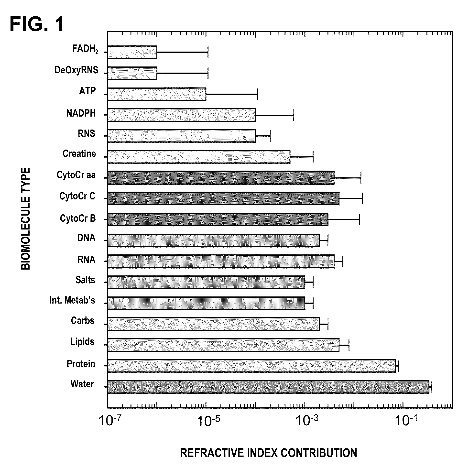
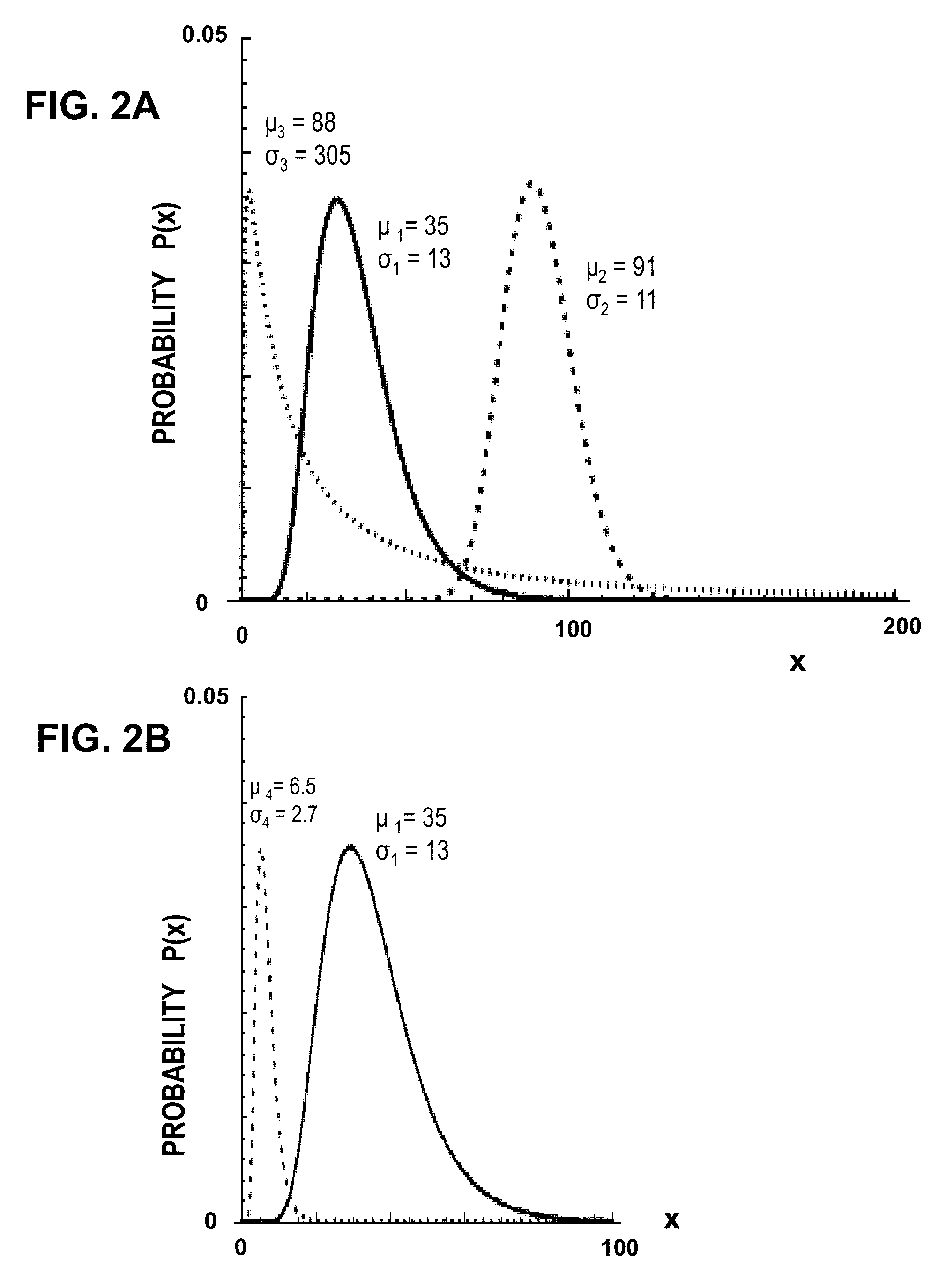
[0037]The invention also describes methods for analyzing bioparticles using resonant cavity devices to determining statistical properties of an optical parameter called Δλ that is related to the biomolecular composition of the bioparticles. This enables a powerful analytical tool for studying disease in general in cells and organelles. Unlike any other single chemical or biophysical measurement, Δλ is a measure of the overall biophysical state of the cell and organelles. The biophysical state of a cell is a reflection of its sum total of changes in biomolecular composition and organization. These properties can be used to differentiate normal and abnormal states of the particles by measuring distributions of optical properties among a population. It can also be used to identify healthy and diseased or stressed states of bioparticles derived from living cells or tissues.
[0038]The invention also provides a simple apparatus for multiple measurements, including size, morphology, and ind...
PUM
| Property | Measurement | Unit |
|---|---|---|
| wavelengths | aaaaa | aaaaa |
| wavelengths | aaaaa | aaaaa |
| size | aaaaa | aaaaa |
Abstract
Description
Claims
Application Information