High duty cycle ion spectrometer

a spectrometer and high-duty cycle technology, applied in the field of ion spectrometers, can solve the problems of wasting ions during the analysis cycle, wasting ions, etc., and achieve the effects of improving the ion ejection energy, speeding up the ejection efficiency, and being less dependen

Active Publication Date: 2015-06-23
THERMO FISHER SCI BREMEN
View PDF13 Cites 6 Cited by
  • Summary
  • Abstract
  • Description
  • Claims
  • Application Information

AI Technical Summary

Benefits of technology

[0009]Hence, ions that are not required by the analyzer are not wasted, but can instead be stored for ejection at a suitable instant. This can also improve the dynamic range of the spectrometer, since the analyzer can be filled to its space charge capacity limit with more ions within the analysis range. This also allows a detection limit to be reached in a shorter space of time.
[0041]A curved axis may provide the benefit of accelerated transfer of ions from the cooling guide towards a quadrupole mass filter or other device. The offset angle might also appear as the result of any remaining axial energy, especially at low gas pressure, or the focusing action of ion optics during transfer.

Problems solved by technology

Hence, such analyzers waste any ions that are not of the mass to charge ratio being transmitted, since these ions are lost.
The use of continuous ion sources, such as electrospray ionisation sources, may mean that ions are wasted when the analyser duty cycle is so low.

Method used


Image

  • High duty cycle ion spectrometer
  • High duty cycle ion spectrometer
  • High duty cycle ion spectrometer

Examples


first embodiment

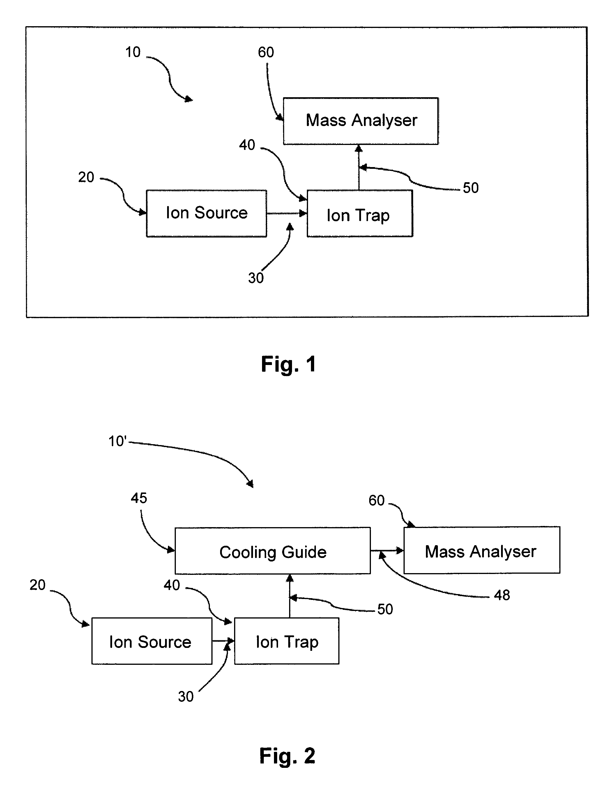
[0050]Referring first to FIG. 1, there is shown a schematic diagram illustrating the present invention.

[0051]A mass spectrometer 10 comprises an ion source 20; an ion trap 40; and a sequential scanning mass analyser 60. The ion source 20 generates ions 30 continuously with a first range of mass to charge ratios. The ion trap 40 receives ions 30 continuously with the first range of mass to charge ratios and orthogonally ejects ions 50 with a second range of mass to charge ratios. The second range of mass to charge ratios is narrower than the first range of mass to charge ratios. The ions 50 are then received by the sequential scanning mass analyser 60 for analysis.

second embodiment

[0052]Referring next to FIG. 2, there is shown a schematic diagram illustrating the present invention.

[0053]A mass spectrometer 10′ comprises an ion source 20; an ion trap 40; a cooling guide 45 and a sequential scanning mass analyser 60. The ion source 20 generates ions 30 with a first range of mass to charge ratios. The ion trap 40 receives ions 30 with the first range of mass to charge ratios and orthogonally ejects ions 50 with a second range of mass to charge ratios to the cooling guide 45. The second range of mass to charge ratios is narrower than the first range of mass to charge ratios. The cooling guide 45 cools the received ions 50, without substantial fragmentation. The energy of the ions is typically reduced to a few eV or even to less than 1 eV. Cooled ions 48 are ejected axially to the sequential scanning mass analyser 60 for analysis.

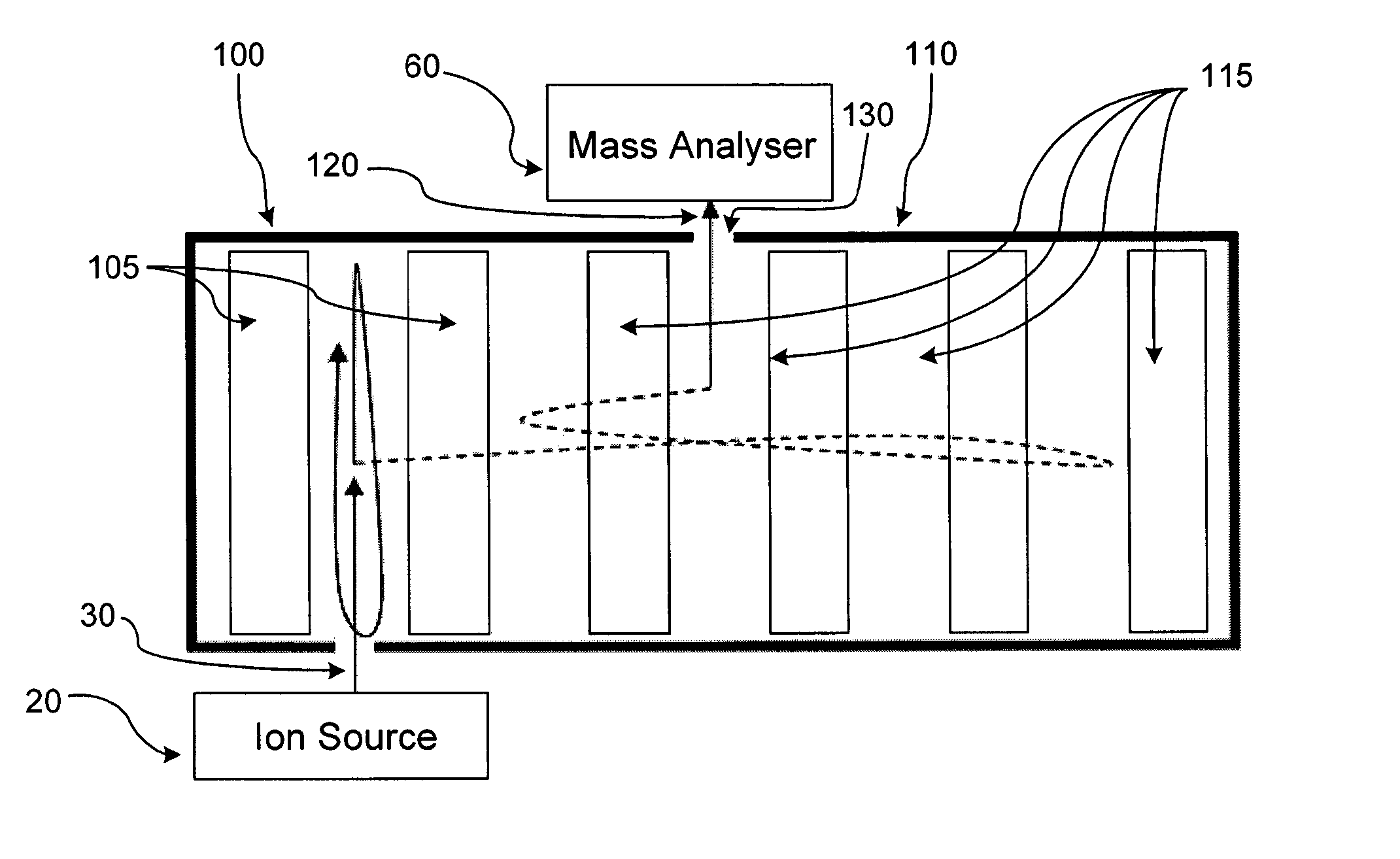
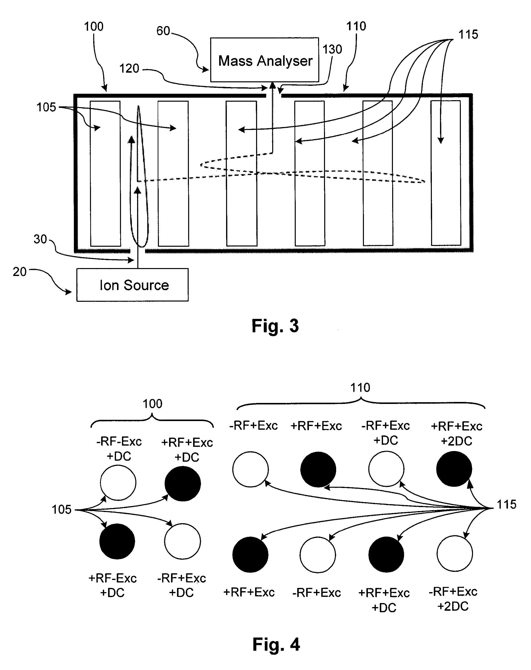
[0054]Referring now to FIG. 3, there is shown a top view of an embodiment of the present invention according to the schematic diagrams o...


PUM

PropertyMeasurementUnit
ion currentaaaaaaaaaa
average ion currentaaaaaaaaaa
mass to charge ratiosaaaaaaaaaa

Abstract

An ion spectrometer is provided, comprising: an ion source, arranged to generate ions continuously with a first range of mass to charge ratios; and an ion trap, arranged to receive ions from the ion source along an axis, and to eject ions with a second range of mass to charge ratios orthogonally to that axis, the second range of mass to charge ratios being narrower than the first range of mass to charge ratios. In some embodiments, ions generated by the ion source continuously flow into the ion trap. Additionally or alternatively, ion optics receive ions ejected from the ion trap and cool the ions without substantial fragmentation. An ion analyzer receives ions ejected from the ion trap or ion optics and separates the ions in accordance with at least one characteristic of the ions.

Description

CROSS-REFERENCE TO RELATED APPLICATIONS[0001]This application is the United States National Stage Application, under 35 USC 371, of International Application No. PCT / EP2012 / 073640 having an international filing date of Nov. 26, 2012 and designating the United States, which claims priority to GB 1120307.2, filed Nov. 24, 2011, said applications incorporated by reference herein in their entireties.TECHNICAL FIELD[0002]This invention relates to an ion spectrometer (such as an ion mobility spectrometer) or a mass spectrometer particularly comprising a sequential scanning mass analyzer, such as quadrupole mass filter, magnetic sector, multi-reflection time-of-flight and electrostatic trap mass analyzers.BACKGROUND TO THE INVENTION[0003]Modern continuous ion sources provide up to 109 ions per second in the case of Electrospray Ionisation (ESI), photoionisation (PI) and Atmospheric Pressure Chemical Ionisation (APCI) sources, up to 1010 ions per second in the case of Electron Ionisation (E...

Claims


Application Information

Patent Timeline
Patent Type & Authority Patents(United States)
IPC IPC(8): H01J49/00H01J49/06H01J49/42H01J49/04G01N27/62
CPCH01J49/063H01J49/06H01J49/427H01J49/4295H01J49/0481H01J49/423H01J49/0031H01J49/426G01N27/622H01J49/10G01N27/623H01J49/0027H01J49/4215H01J49/425H01J49/401
Inventor MAKAROV, ALEXANDER ALEKSEEVICH
Owner THERMO FISHER SCI BREMEN
Why Eureka
Try Eureka