
Electrical power supply device for powering at least one piece of equipment of an aircraft rotor, and an aircraft

a technology of electric power supply device and rotor, which is applied in the direction of dynamo-electric machines, rotocraft, electrical apparatus, etc., can solve the problems of difficult to deliver electrical power to equipment, difficult to install slip rings, and unfavorable changes in the aerodynamic profile of such surfaces, etc., to achieve the effect of blindness, easy to perform, and fast operation

Inactive Publication Date: 2015-06-30
EUROCOPTER
View PDF17 Cites 1 Cited by
  • Summary
  • Abstract
  • Description
  • Claims
  • Application Information

AI Technical Summary

Benefits of technology

The solution provides a reliable, lightweight, and easy-to-maintain power supply system that reduces friction-related wear and allows for efficient electricity transfer, optimizing manufacturing and reducing downtime for maintenance, while being compact enough to fit within a small-diameter mast.

Problems solved by technology

The problem of such airfoil surfaces icing is well known in the aviation industry, it being possible for the aerodynamic profile of such surfaces to be modified unfavorably as a result of ice forming in flight because of impacts against droplets of supercoiled water contained in the atmosphere.
However, it will be understood that it can be difficult to deliver electrical power to equipment present on a rotary assembly from an electricity generator that is present in a stationary frame of reference within the airframe of the aircraft.
Nevertheless, such a slip ring unit is very heavy and difficult to put into place, in particular because of the presence of a large number of electrical cables of large dimensions and because of the presence of the slip rings themselves.
Furthermore, friction between each brush and the corresponding slip ring tends to degrade the performance of the slip ring unit.
Unfortunately, the slip ring unit is sometimes difficult to access, so the cost of maintenance can be high and the rotorcraft can be out of service for a long time.

Method used


Image

  • Electrical power supply device for powering at least one piece of equipment of an aircraft rotor, and an aircraft
  • Electrical power supply device for powering at least one piece of equipment of an aircraft rotor, and an aircraft
  • Electrical power supply device for powering at least one piece of equipment of an aircraft rotor, and an aircraft

Examples


first embodiment

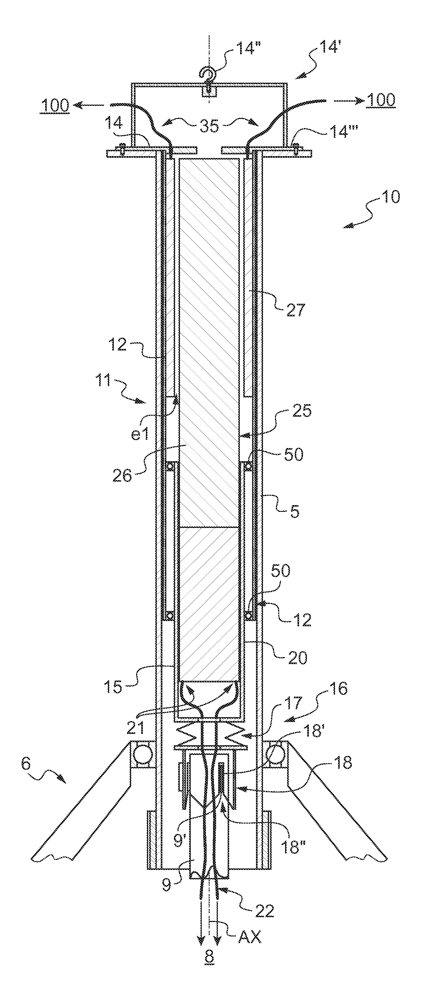
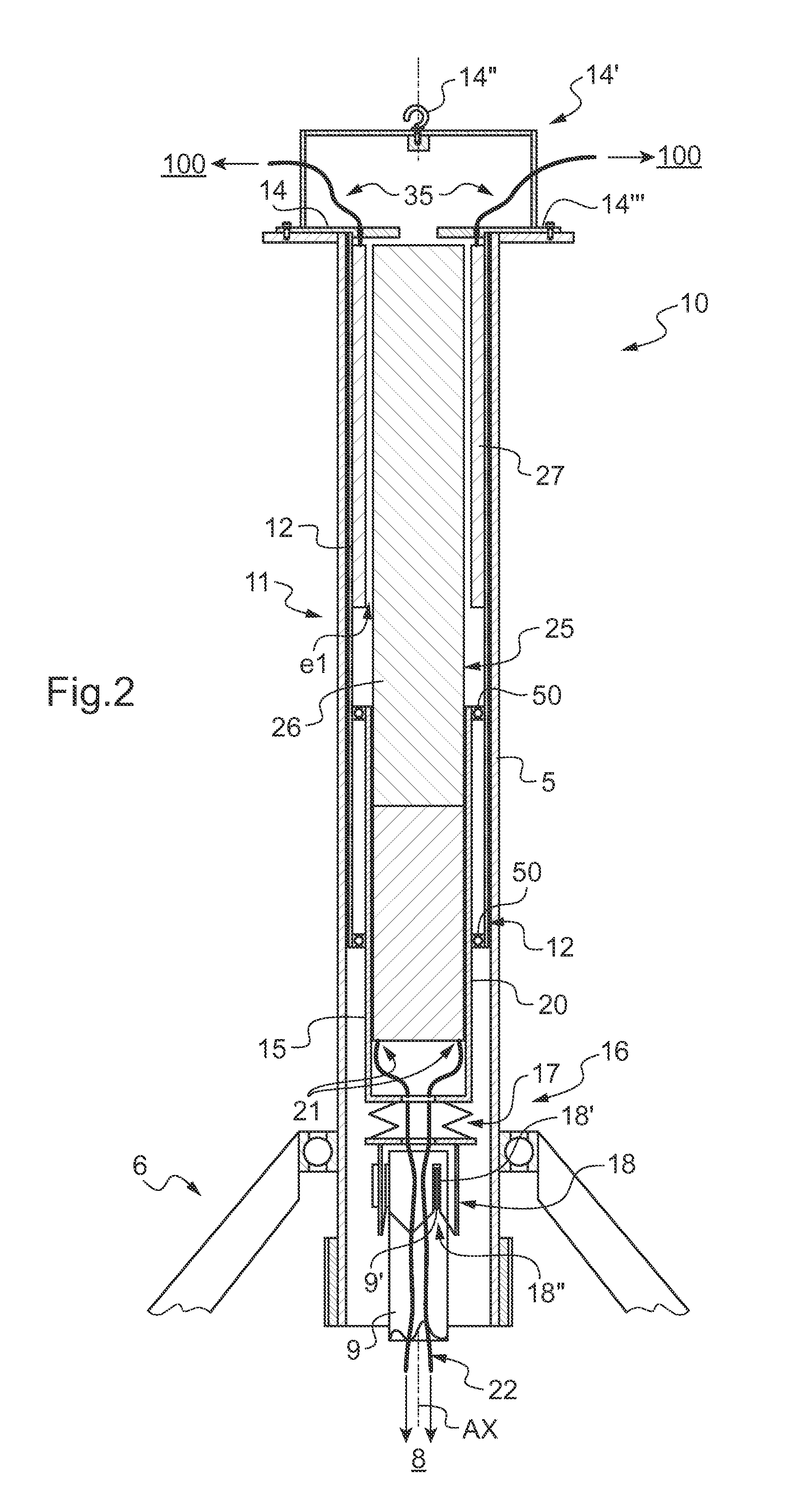
[0095]FIG. 2 shows an electrical power supply device 10 in a

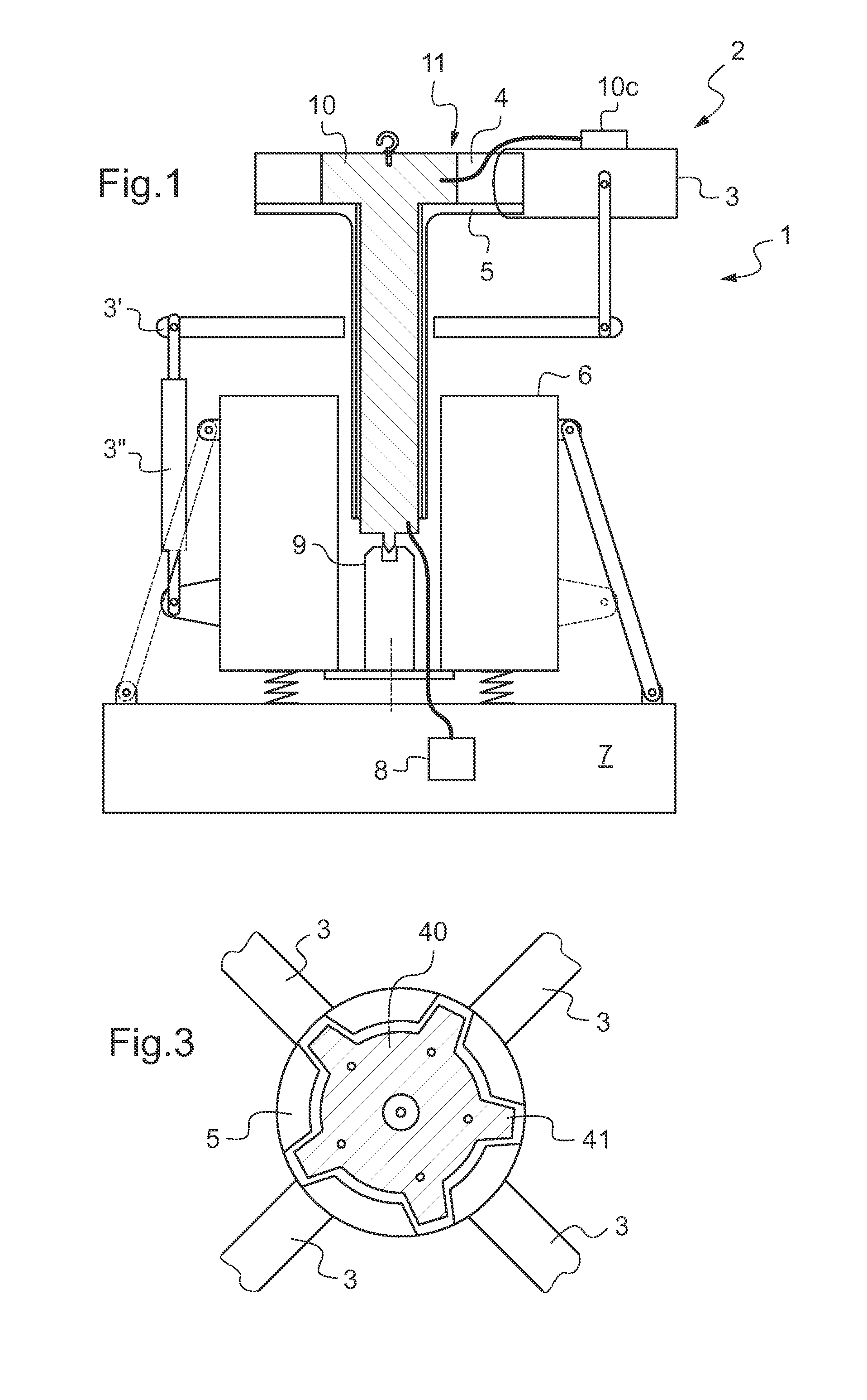
[0096]Independently of the embodiment, the pole 11 comprises a rotary casing 12 suitable for being fastened to the mast 5 via fastener means 14.

[0097]The fastener means may comprise a projecting collar 14″′ screwed to a shoulder of the mast 5, for example. In addition, the collar 14″′ may include lifting means 14′ fitted with a lifting hook 14″.

[0098]With reference to FIG. 3, the device 10 may include upper fuse means comprising a wheel 40 interposed between the collar 14″′ of the pole 11 and the mast 5. This wheel has specifically the function of minimizing the risk of the rotor jamming in the event of at least one member of the pole 11 jamming. This wheel 40 is thus fastened to the collar and co-operates by interfering shapes with a rotary member of the rotor.

[0099]For example, the wheel 40 has a plurality of teeth 41 received in hollow spaces in the mast 5. In addition, the wheel 40 is made from a flexible material selec...

second embodiment

[0128]In FIG. 4, the pole 11 nevertheless possesses a rotary converter 30 that is powered electrically by the secondary member 27 of the transformer.

[0129]The rotary converter 30 is then secured to the rotary casing 12. For example, the rotary converter is arranged inside the rotary casing 12, possibly being fastened to an inside wall of the rotary casing.

[0130]The rotary converter is then provided with an outlet 31 suitable for being connected to electrical equipment 100 of the rotor.

[0131]Such a rotary converter 30 may be used in particular for converting the AC from the transformer 25 into DC.

[0132]Furthermore, in a first variant shown in FIGS. 2 and 4, the primary and secondary members are coaxial, one being engaged inside the other.

[0133]In this variant, the secondary member 27 surrounds the primary member 26 at least in part, with an annular airgap e1 lying between the secondary member 27 and the primary member 26.

[0134]In the second variant of FIG. 5, the primary member and t...


PUM


Abstract

An electrical power supply device (10) comprising a pole (11), said pole (11) having a non-rotary casing (15) and a rotary casing (12) provided with fastener means (14) for fastening to a mast. The pole (11) includes a non-rotary converter (20) fastened to the non-rotary casing (15) and generating AC at a frequency higher than one kilohertz. The pole also includes a rotary transformer (25), said rotary transformer (25) having a primary member (26) secured to the non-rotary casing (15) and a secondary member (27) secured to the rotary casing (12), the primary member (26) being connected to the non-rotary converter (20) to receive said AC, and the secondary member (27) being suitable for electrically powering equipment (100) of a rotor (2).

Description

CROSS REFERENCE TO RELATED APPLICATIONS[0001]This application claims priority to French patent application No. FR 12 / 01410 filed on May 16, 2012, the content of which is incorporated herein.BACKGROUND OF THE INVENTION[0002](1) Field of the Invention[0003]The present invention relates to a device for electrically powering at least one piece of equipment of a rotor, and also to an aircraft including such a device.[0004]The invention lies in the technical field of means for electrically powering a rotary member, and more particularly de-icing / anti-icing members of a rotorcraft rotor.[0005](2) Description of Related Art[0006]Certain aircraft are provided with devices for de-icing / anti-icing airfoil surfaces, in particular blades of a rotor. The problem of such airfoil surfaces icing is well known in the aviation industry, it being possible for the aerodynamic profile of such surfaces to be modified unfavorably as a result of ice forming in flight because of impacts against droplets of s...

Claims


Application Information

Patent Timeline
Patent Type & Authority Patents(United States)
IPC IPC(8): B64D15/12H02K7/18B64C27/12B64C27/32
CPCB64D15/12H02K7/1823H02K7/1861B64C27/12B64C27/32B64D27/24H02K5/22H02K7/14
Inventor GIORDANO, SERGEBOURGET, VINCENT
Owner EUROCOPTER
Learn More