
Monolith catalyst test system and method for its use

Active Publication Date: 2015-06-30
CATALYTIC COMBUSTION CORP
View PDF18 Cites 4 Cited by
  • Summary
  • Abstract
  • Description
  • Claims
  • Application Information

AI Technical Summary

Benefits of technology

This patent describes a system for testing the activity of monolithic catalysts without damaging them. The system can test a small section of the catalyst while keeping it in place, by directing gas through pipes that are sealed against the surface of the catalyst. The system can be used with different gas compositions and can accommodate different sizes and shapes of catalysts without the need for different tools. The technical effects are efficient and non-destructive testing of monolithic catalysts.

Problems solved by technology

The first method, sampling, has two major disadvantages: sampling error and catalyst damage or failure.
Sampling error comes about because the activity of the catalyst element can vary across its face.
Therefore, the sample core may test at higher or lower activity than the element as a whole and introduce significant sampling error into the test results.
First, because reinstalling the core into the element is challenging, the hole created by the removed sample core is often plugged to prevent flow passing through it.
This reduces the available catalyst volume and detriments the performance of the catalyst element as a whole.
Additionally, any leakage around the plug or reinstalled core impairs performance.
Fear of damaging the element leads people to test a limited amount of it—and thereby increase sampling error—because every core removed presents another opportunity to damage the overall element.
Second, the process of removing the core can cause loss of coating material in the core itself.
This not only detriments the analysis but because some catalyst elements have layers of metal foil that are not bound together, the element can either fall apart or destroy its cellular structure.
The second method, whole element testing, eliminates sampling error and catalyst failure, but it too has a couple of problems.
First, the method is resource and cost intensive because an engine has to be used to generate the test gas or a synthetic gas mixture must be used.
And the engine also introduces error to the testing because a wide range of factors affect engine exhaust, factors such as engine wear, ambient conditions, fuel quality, and oil quality.
This leads to having a lot of equipment on-hand and the time consuming changeover that results.
In summary, the first method, sampling, introduces significant sampling error and destroys a portion of the catalyst element.
The second method, whole element testing, is very inefficient and difficult to set up given the wide range of sizes and shapes of catalyst elements employed by the industry.

Method used


Image

  • Monolith catalyst test system and method for its use
  • Monolith catalyst test system and method for its use
  • Monolith catalyst test system and method for its use

Examples


Embodiment Construction

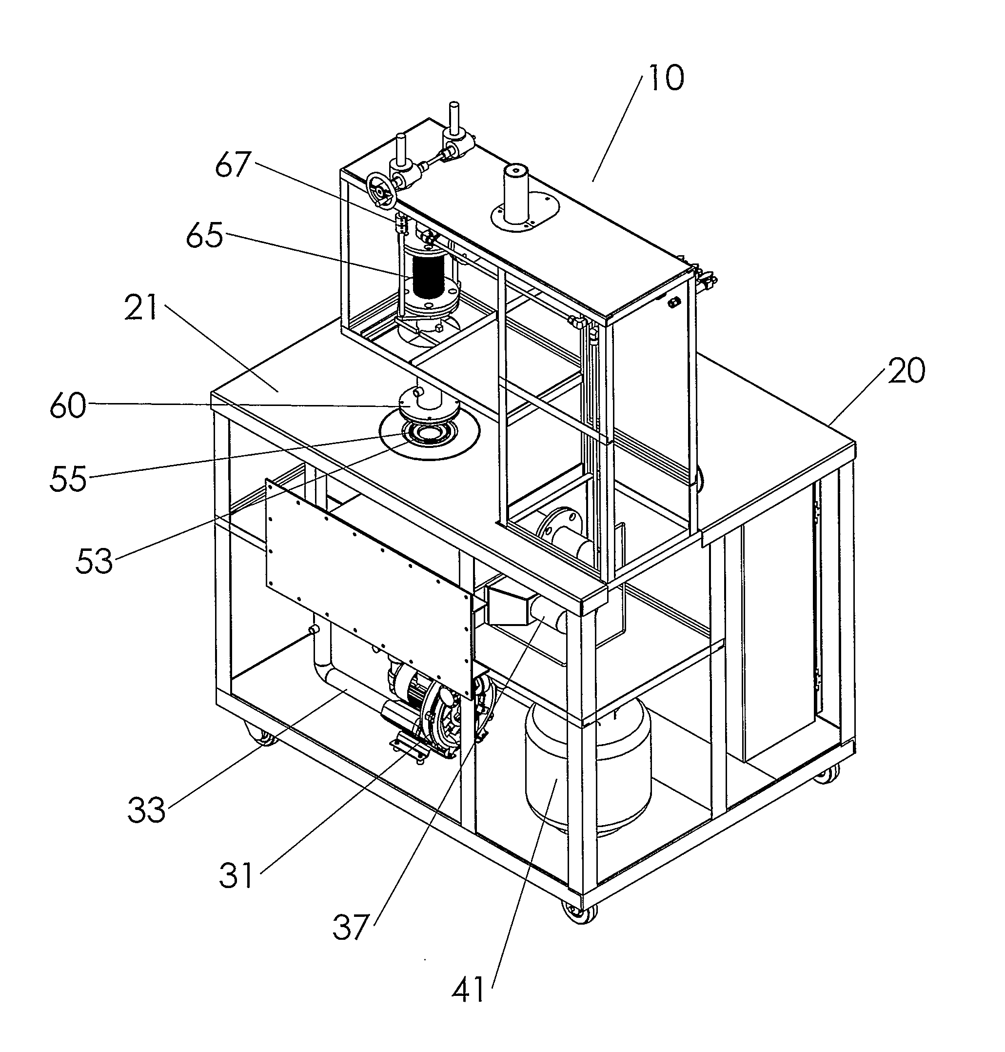
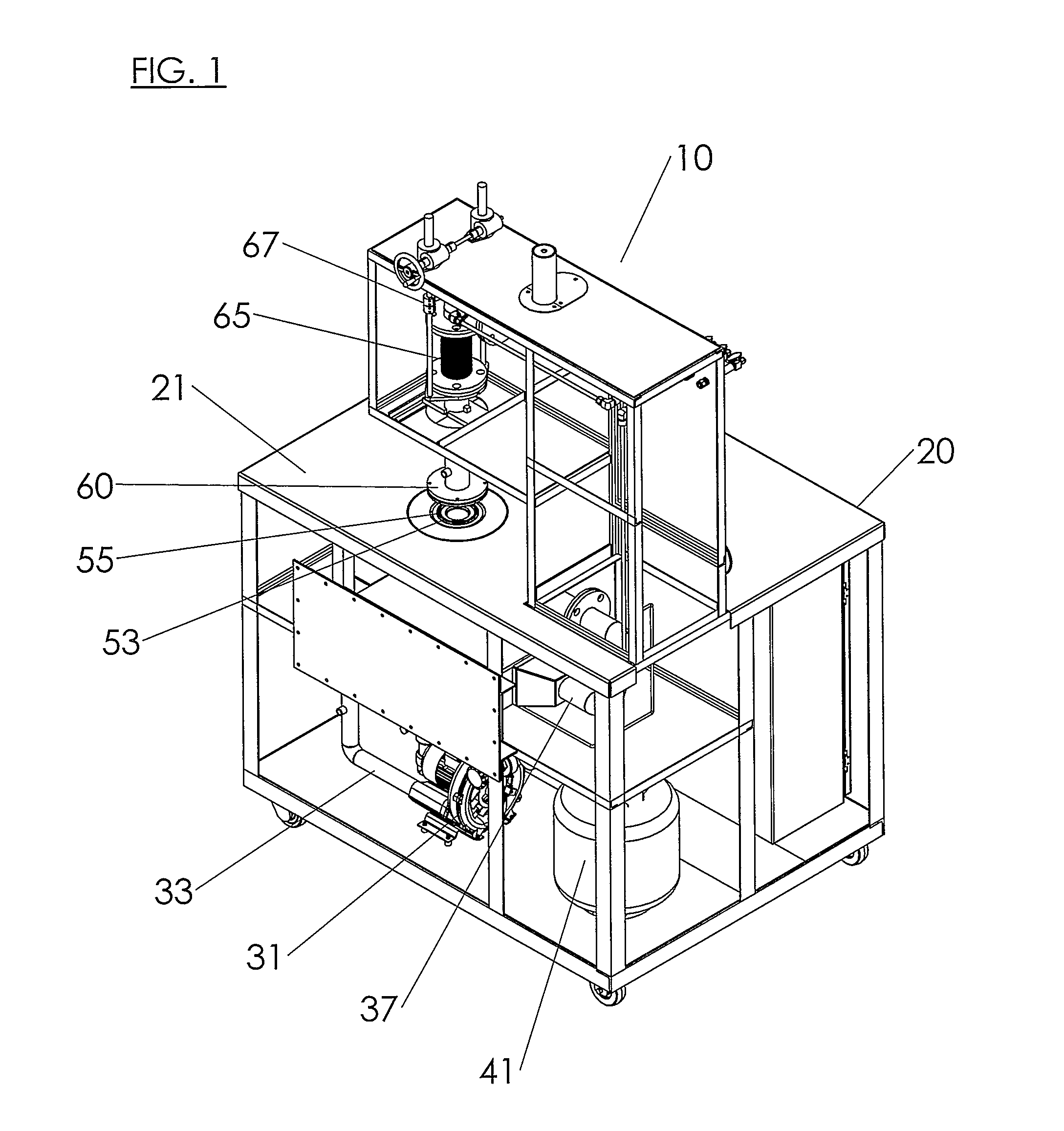
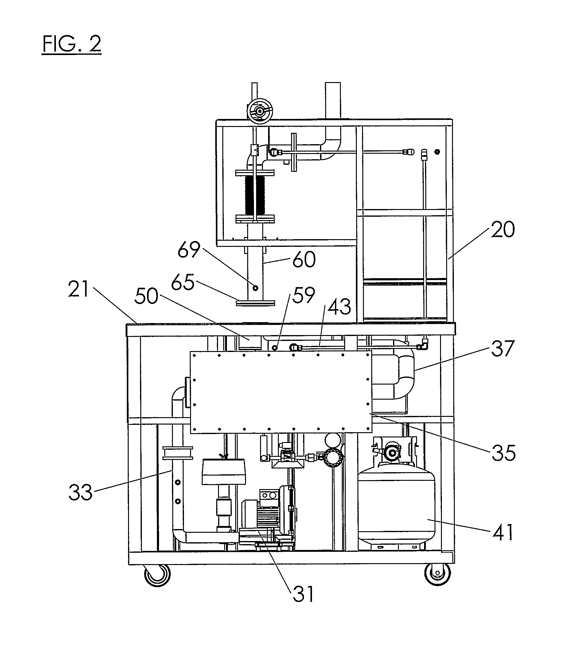
[0036]A test system 10 made according to this invention allows a section of a monolithic catalyst element to be tested without requiring a piece of the catalyst to be removed from the element. Although the system 10 described herein is intended for use catalyst elements typically found in industrial engines, the system 10 could be used to test any monolithic catalyst element for any industry. These elements are especially common in a range of environmental compliance process units.

[0037]Testing is accomplished by providing a means of conveying fluid through the catalyst element and allowing those means to test different areas or sections of the element. A preferred embodiment uses a test stand 20 which includes piping above and below the catalyst as the conveying means, air as the main fluid and propane as the test fluid, that is, the constituent fluid acted upon by the catalyst element. A blower 31 creates the air stream and passes it into a blower outlet piping 33 which is connect...


PUM


Abstract

A system and method for non-destructive testing of a monolith catalyst element includes a flat surface on which a monolith catalyst can be placed and a portion of the catalyst sealed against a piping arrangement located above and below the flat surface. A test fluid passes between the piping and therefore through the portion of the sealed catalyst section. Ports located in the piping allow for sampling of the fluid before and after the catalyst section. The catalyst element may then be repositioned on the flat surface for testing of a second portion of the element.

Description

BACKGROUND OF THE INVENTION[0001]This invention relates generally to systems, apparatuses, and methods useful in testing the performance of a monolith catalyst. More specifically, this invention relates to systems, apparatuses, and methods for non-destructive testing of a monolith catalyst like those used in industrial engine emission control. Notwithstanding the above, the underlying principles could be used for testing any large monolith catalyst element.[0002]There are two methods for testing the activity of a monolith catalyst. The first method removes a small portion of the catalyst element, places that portion or sample core into a small test system, and uses synthetic gas mixtures to test the core and determine the overall activity of the catalyst. For example, catalysts used in industrial engines have outside dimensions from about 6 to 40 inches across and the removed core can be about 1 inch diameter. The second method tests the entire catalyst element by installing the ele...

Claims


Application Information

Patent Timeline
IPC IPC(8): G01N31/10
CPCG01N31/10F01N2900/0406B01J2219/2428F01N2550/02F01N2900/1621
Inventor ROBINSON, JR., JOHN W.VERDEGAN, DON R.WERNER, MIKE J.
Owner CATALYTIC COMBUSTION CORP
Learn More