Interferometer module

a technology of interferometers and modules, applied in the direction of instruments, electrical appliances, basic electric elements, etc., can solve the problems of internal coherence of beams, not necessarily coherence with respect, etc., and achieve the effect of improving the resolution of measuremen

Active Publication Date: 2015-06-30
ASML NETHERLANDS BV
View PDF34 Cites 3 Cited by
  • Summary
  • Abstract
  • Description
  • Claims
  • Application Information

AI Technical Summary

Benefits of technology

[0004]According to a first aspect, the present invention provides an interferometer module adapted for emitting a measurement beam and an associated reference beam towards a respective measurement mirror and reference mirror, said interferometer module comprising: a beam combiner for combining a reflection of said measurement beam and said reference beam into a combined beam, a non-polarizing beam splitter for splitting said combined beam into a first split beam and a second split beam, each split beam comprising a component of said reference beam and said measurement beam, a first polarizing beam splitter, for splitting said first split beam into a first polarized beam having a first polarization and a second polarized beam having a second polarization, a second polarizing beam splitter, for splitting said second split beam into a third polarized beam having a third polarization and a fourth polarized beam having a fourth polarization, a first, second, third and fourth detector for detecting a beam energy of said first, second, third and fourth polarized beams respectively, wherein said polarizations of said first, second, third and fourth polarized beams are different polarizations. The four detectors provide four interference signals wherein each interference signal is typically a sinusoid signal shifted in phase relative to the other signals. It is thus possible to determine a direction of displacement between said measurement mirror and said reference mirror. Moreover, by using interpolating methods between the four signals, the resolution of the measurement may be improved. The coherent beams are internally coherent but are not necessarily coherent with respect to each other. The combined beams are formed by reflected reference and associated reflected measurement beams, which at least partially coincide at their corresponding beam detector.
[0012]In an embodiment said non-polarizing beam splitter is fixedly attached to said first polarizing beam splitter and / or to said second polarizing beam splitter using an optically neutral adhesive. The non-polarizing beam splitter and the first and second polarizing beam splitters may thus be formed as a macro-element. Besides a lower sensitivity to vibrations and / or misalignment, the use of such an optically neutral adhesive reduces the loss of light which occurs when a light beam traverses multiple interfaces between materials having different refractive indices.
[0017]In an embodiment the beam splitter unit is adapted for emitting said three measurement beams non-coplanarly, and / or for emitting said three reference beams non-coplanarly. The interferometer module according to the invention thus makes it possible to determine a displacement between said mirrors along a direction x, and a rotation around directions Rz and Rz which are perpendicular to each other and to direction x.
[0024]In an embodiment the inside of said module is substantially filled with a solid material, preferably a cured epoxy-resin, more preferably Stycast®. As the optical elements of the module are thus securely held in place, the module is less susceptible to alignment errors due to vibrations or handling.

Problems solved by technology

The coherent beams are internally coherent but are not necessarily coherent with respect to each other.

Method used


Image

  • Interferometer module
  • Interferometer module
  • Interferometer module

Examples


Embodiment Construction

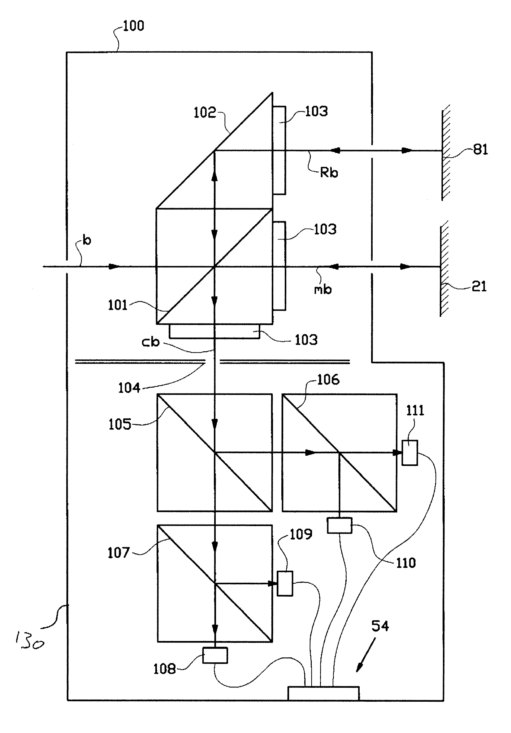
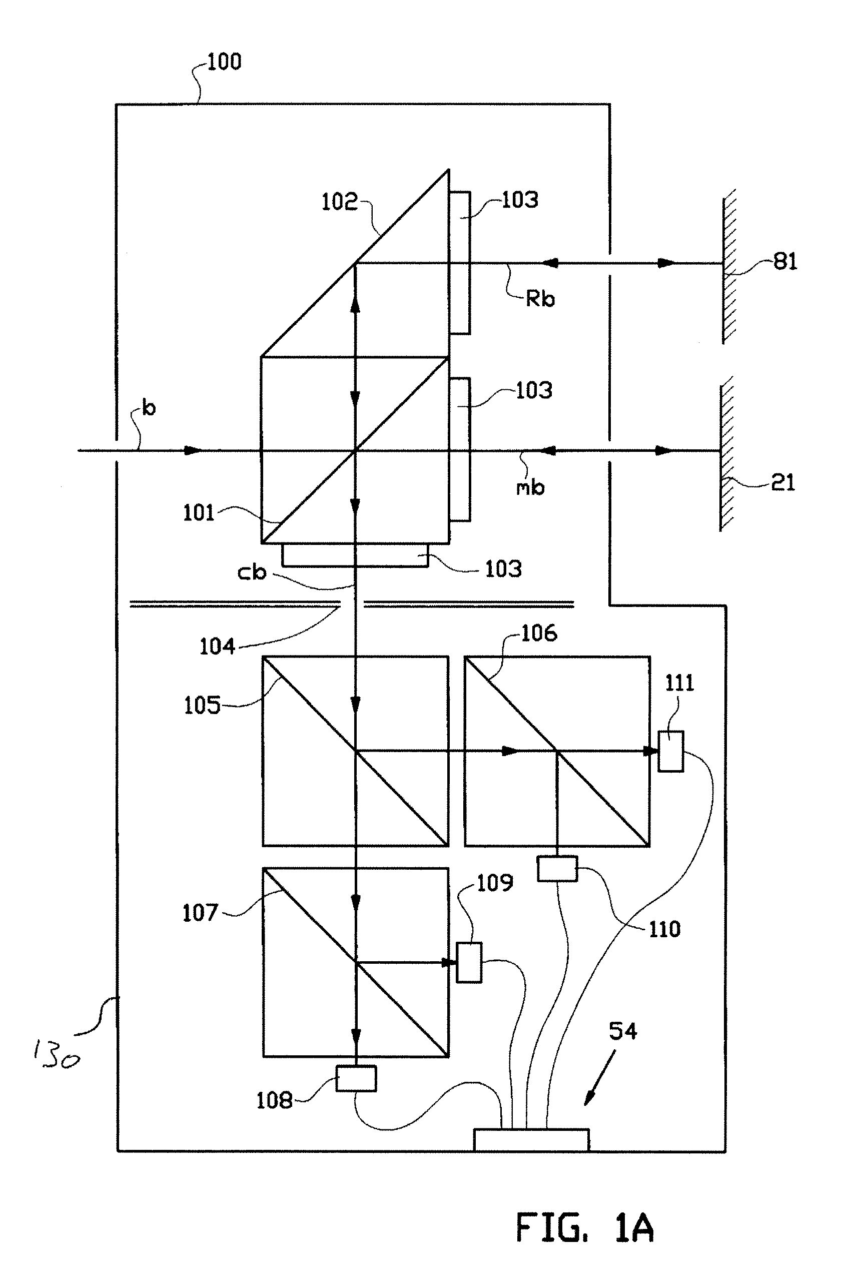
[0043]FIG. 1A shows a detail of a preferred embodiment of an interferometer module 100 according to the present invention. A single coherent beam b is emitted onto polarizing beam splitter 101, which splits the beam b into a polarized measurement beam Mb and an associated polarized reference beam Rb. After having passed the polarizing beam splitter 101, the measurement beam Mb passes a quarter wave plate 103. The incident measurement beam is then reflected back by first mirror 21, and again passes the quarter wave plate 103. Subsequently the reflected measurement beam is reflected through an iris 140 by the polarizing beam splitter 101.

[0044]Similarly, the part of the coherent beam that forms the reference beam Rb is reflected by prism 102 through a quarter wave plate 103 and incident on second mirror 81. The reference beam Rb is then reflected back by mirror 81 and again passes through the same quarter wave plate 103, after which it is reflected by prism 102, through polarizing bea...


PUM

PropertyMeasurementUnit
angleaaaaaaaaaa
distanceaaaaaaaaaa
distances d1,d2,d3,d4aaaaaaaaaa

Abstract

The invention relates to a differential interferometer module adapted for measuring a direction of displacement between a reference mirror and a measurement mirror. In an embodiment the differential interferometer module is adapted for emitting three reference beams towards a first mirror and three measurement beams towards a second mirror for determining a displacement between said first and second mirror. In a preferred embodiment the same module is adapted for measuring a relative rotation around two perpendicular axes as well. The present invention further relates to a lithography system comprising such a interferometer module and a method for measuring such a displacement and rotations.

Description

BACKGROUND[0001]The invention relates to an interferometer module adapted for measuring a displacement between a reference mirror, for instance provided on the optical column of an exposure tool, and a measurement mirror, for instance provided on a target carrier of the exposure tool which is moveable relative to the optical column. The invention further relates to lithography system comprising such an interferometer module, and a method for measuring such a displacement.[0002]U.S. Pat. No. 7,224,466 provides a compact differential interferometer for measuring a displacement between a measurement mirror and a reference mirror along two axes. The interferometer uses shared measurement and reference beams that respectively reflect from measurement and reference mirrors before that shared beams are split into individual beams corresponding to the measurement axes of the interferometer. By essentially reflecting the measurement beam and reference beam twice in the respective measurement...

Claims


Application Information

Patent Timeline
Patent Type & Authority Patents(United States)
IPC IPC(8): G01B9/02G03F7/20
CPCG03F7/70775G03F7/70833G03F7/7085H01J2237/30438G01B9/02011G01B9/02012G01B9/02027G02B27/283G03F7/70591H01L21/0274H01J2237/3175G01B9/02016G03F7/20G01B9/02007G01B9/02015
Inventor DE BOER, GUIDOOOMS, THOMAS ADRIANVERGEER, NIELSCOUWELEERS, GODEFRIDUS CORNELIUS ANTONIUS
Owner ASML NETHERLANDS BV
Why Eureka
Try Eureka