Memristor device with resistance adjustable by moving a magnetic wall by spin transfer and use of said memristor in a neural network

a technology of resistance and magnetic wall, applied in the direction of information storage, static storage, digital storage, etc., can solve the problems of low operating speed, device fragility, and inability to quickly perform seemingly simple processes by most powerful computers using the most advanced algorithms. to achieve the effect of limiting the risk of component deterioration

Active Publication Date: 2015-06-30
CENT NAT DE LA RECHERCHE SCI +1
View PDF21 Cites 8 Cited by
  • Summary
  • Abstract
  • Description
  • Claims
  • Application Information

AI Technical Summary

Benefits of technology

[0017]The other main advantages of the invention are that, by using the effect of magnetoresistance, it provides a resistance having a value that can be adjusted quickly and up to very high values. Indeed, it has recently been demonstrated that a wall pushed by spin transfer can reach 175 m / s. This means that the resistance of a sub-micrometric memristor according to the invention based on spin transfer may be adjusted by current injection lasting several nanoseconds or less.
[0018]Finally, the invention limits the risk of deterioration of the component, because the current densities used to move the magnetic wall by spin transfer are less than 108 A.cm−2 (amps / cm2), i.e. well below those used in electromigration techniques.

Problems solved by technology

Nonetheless, even the most powerful computers using the most advanced algorithms are unable to quickly perform apparently simple processes, such as image interpretation, that are however performed in a fraction of a second by the human brain.
Unfortunately, this ion electromigration effect involves high operating temperatures and therefore a potential fragility of the device.
Above all, however, this ion electromigration effect results in low operating speeds, since it is related to the mobility of the ions: the resistance of Hewlett-Packard memristors changes very slowly.
Surprisingly, this last publication gives no implementation details, since the realization of a memristor using a spin valve is difficult to imagine.
Consequently, a spin valve can only provide low-value resistance.
This is why the realization of a memristor using a spin valve is difficult to envisage.
Unfortunately, this device does not make it possible to continuously vary the resistance within a range, since the magnetic wall only has two stable positions to which they gravitate irremediably.

Method used


Image

  • Memristor device with resistance adjustable by moving a magnetic wall by spin transfer and use of said memristor in a neural network
  • Memristor device with resistance adjustable by moving a magnetic wall by spin transfer and use of said memristor in a neural network
  • Memristor device with resistance adjustable by moving a magnetic wall by spin transfer and use of said memristor in a neural network

Examples


Embodiment Construction

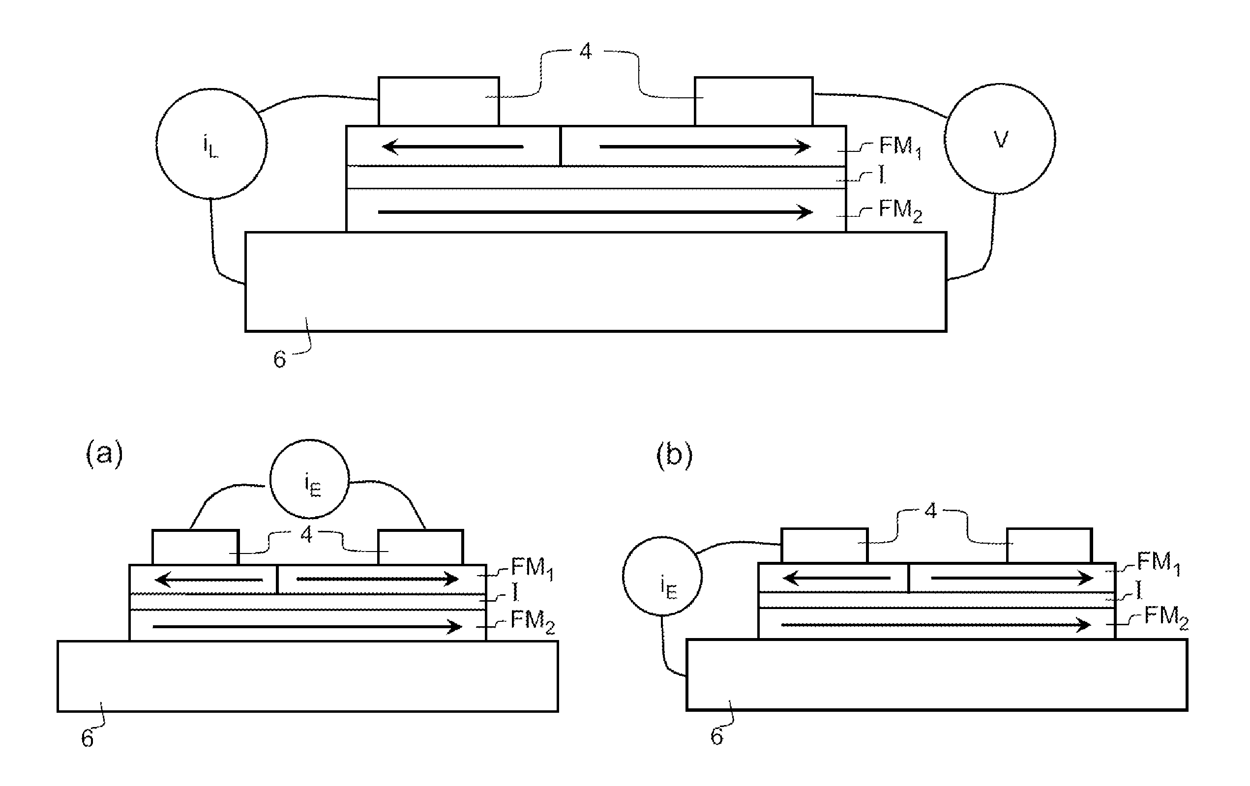
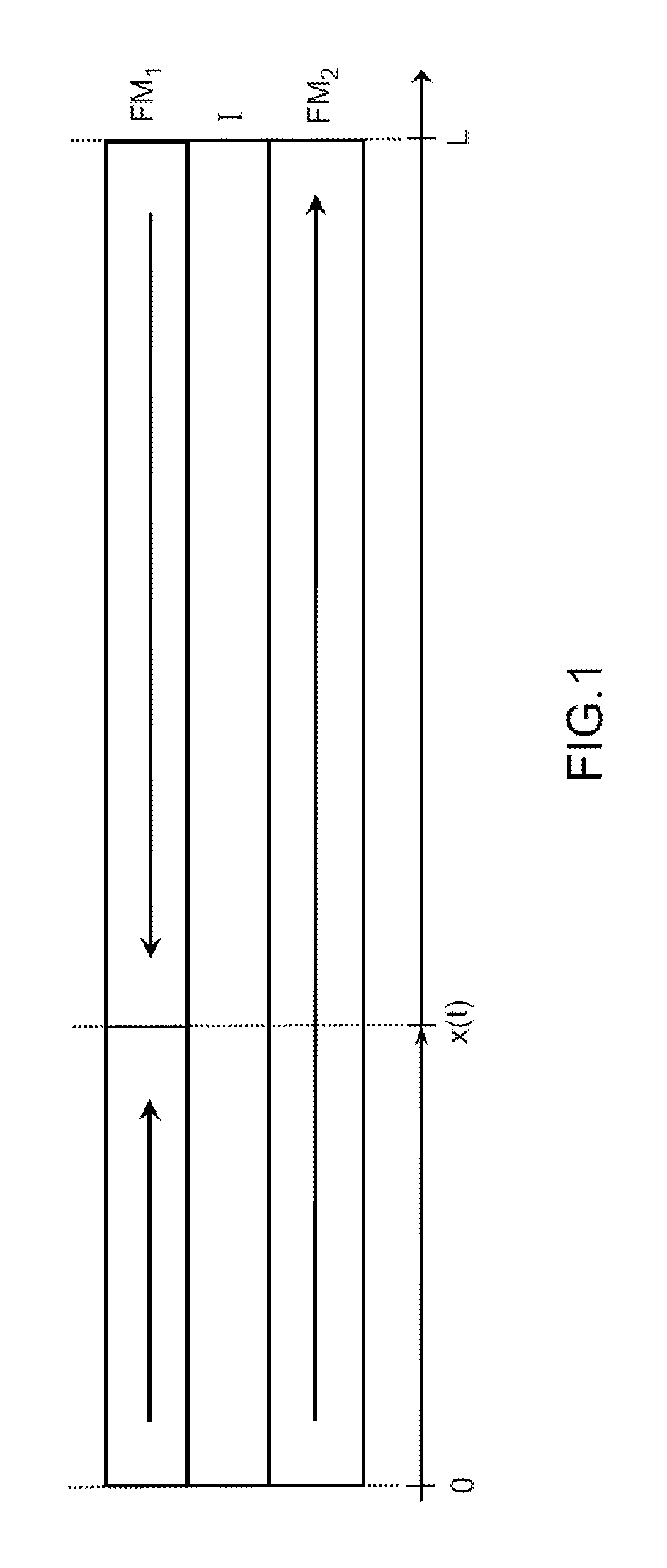
[0028]FIG. 1 is a schematic diagram of an example magneto-resistive memristor according to the invention, comprising two magnetic elements FM1 and FM2 forming elongate layers of length L, the elements FM1 and FM2 being separated by a non-magnetic element I also forming an elongate layer of length L. The layer I is an insulant or a semi-conductor. The direction of magnetization of the two magnetic layers FM1 and FM2 are shown by arrows. Thus, in the case of FIG. 1, a magnetic wall is present in FM1 at a position x which may vary over time t, while the magnetization is homogeneous in FM2, which has no magnetic wall.

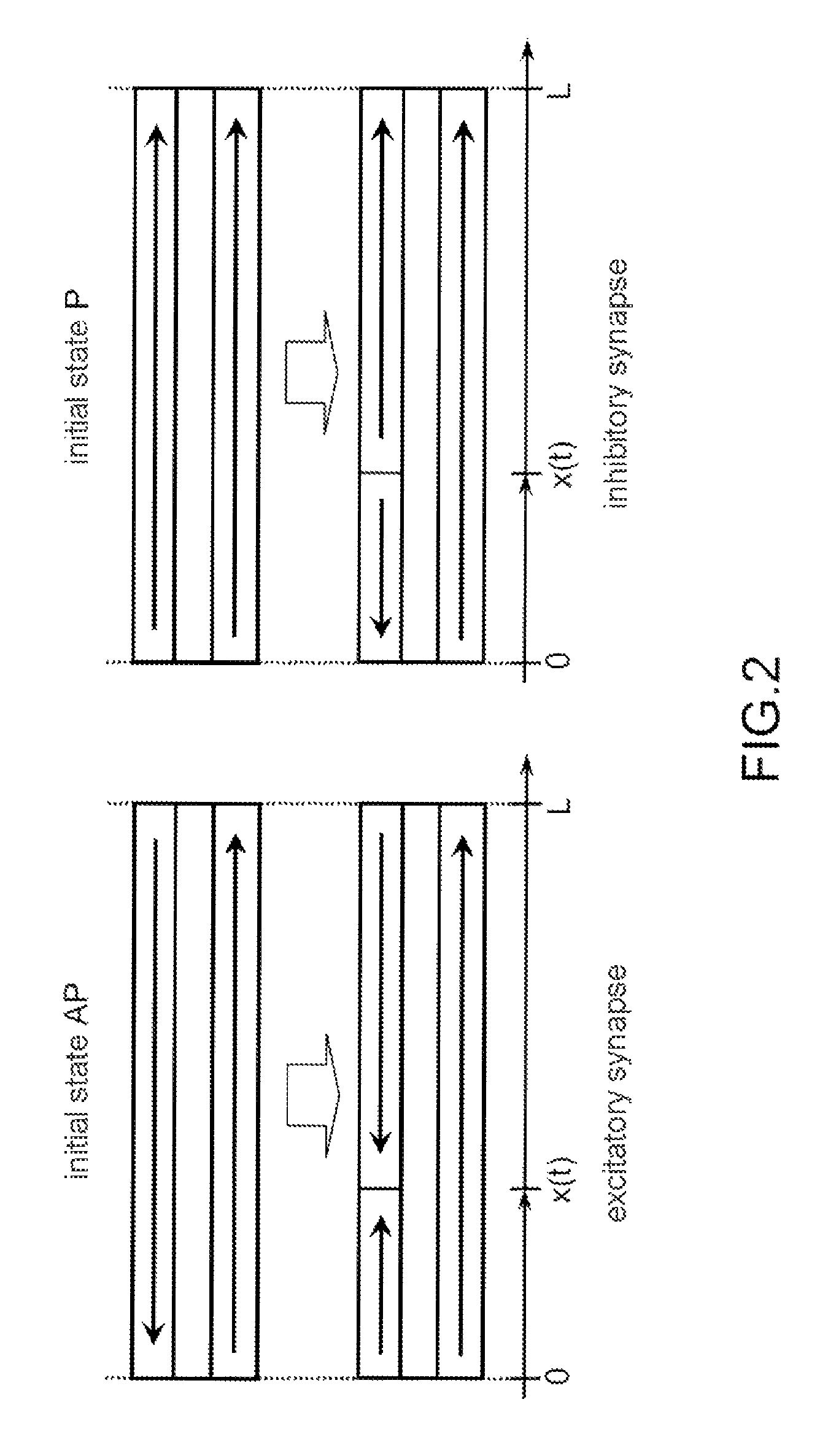
[0029]The resistance R of such a magneto-resistive structure is different depending on the arrangement of the magnetizations in the two layers. If the magnetizations are oriented in the same direction, the arrangement is referred to as “parallel”, i.e. both arrows in the same direction in FIG. 1, and the resistance is noted as R═RP. If the magnetizations are oriented in opp...


PUM


Abstract

A device with adjustable resistance includes two magnetic elements separated by an insulating or semi-conductor element. The resistance of the device depends on the position of a magnetic wall in one of the magnetic elements, the magnetic wall separating two areas of said magnetic element each having a separate homogeneous direction of magnetization. The device comprises means for moving the magnetic wall in the magnetic element by applying a spin-polarized electric current, such that the resistance of the device is adjustable in a continuous range of values. The invention is useful in neuromimetic circuits, neural networks and bio-inspired computers.

Description

CROSS REFERENCE TO RELATED APPLICATION[0001]This application is a National Stage of International patent application PCT / EP2010 / 055902, filed on Apr. 30, 2010,which claims priority to foreign French patent application No. FR 0902122, filed on Apr. 30, 2009, the disclosures of which are incorporated by reference in their entirety.FIELD OF THE INVENTION[0002]The present invention relates to an adjustable-resistance device, commonly called a memristor, that works through the movement of a magnetic wall by spin transfer. It is used for example in the field of chip-based neural network neuromimetic circuits and more generally in bio-inspired computer architecture.BACKGROUND[0003]In the last fifty years, purely digital Von Neumannian computing has progressed considerably. Nonetheless, even the most powerful computers using the most advanced algorithms are unable to quickly perform apparently simple processes, such as image interpretation, that are however performed in a fraction of a seco...

Claims


Application Information

Patent Timeline
Patent Type & Authority Patents(United States)
IPC IPC(8): G11C11/00G11C11/16G11C11/54G11C11/14
CPCG11C11/16G11C11/54G11C11/14G11C11/161G11C11/1675
Inventor GROLLIER, JULIECROS, VINCENTNGUYEN VAN DAU, FREDERIC
Owner CENT NAT DE LA RECHERCHE SCI
Why Eureka
Try Eureka