Gain calibration for a timing error detector

a timing error and detector technology, applied in the field of electronic devices, to achieve the effect of removing unpredictability and less power

Active Publication Date: 2015-06-30
MICROSEMI STORAGE SOLUTIONS
View PDF25 Cites 0 Cited by
  • Summary
  • Abstract
  • Description
  • Claims
  • Application Information

AI Technical Summary

Benefits of technology

[0018]Baud rate sampling architectures intrinsically use less power than systems sampling at twice or more the baud rate. In many serializer / deserializer (SerDes) applications, the jitter tolerance requirements have often eliminated the possibility of using baud rate sampling and Mueller-Muller based timing recovery methods due to the unpredictability in the resulting loop response. Embodiments of the invention can provide a way to remove the unpredictability, thus making Mueller-Muller timing recovery methods feasible.
[0019]In applications in which sharing a secondary timing path among two or more main data paths is feasible, a second benefit of reduced silicon area is realized. Consider the case of a system with 4 receive signals. In a classic approach with the received signal sampled at twice the baud rate, 4 analog-to-digital converters (ADCs) sampling at twice the baud rate are used, or 8 ADCs sampling at the baud rate with the outputs interleaved to provide the 4 separate data streams at twice the baud rate are used. Embodiments of the invention can advantageously have an architecture using only 5 ADCs sampling at the baud rate, corresponding to the 4 main data paths and a single shared secondary timing path.

Problems solved by technology

In many serializer / deserializer (SerDes) applications, the jitter tolerance requirements have often eliminated the possibility of using baud rate sampling and Mueller-Muller based timing recovery methods due to the unpredictability in the resulting loop response.

Method used


Image

  • Gain calibration for a timing error detector
  • Gain calibration for a timing error detector
  • Gain calibration for a timing error detector

Examples


Embodiment Construction

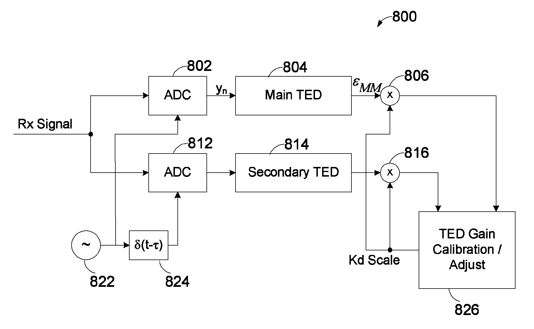
[0037]The standard Mueller-Muller timing error detector (TED) for baud rate sampling receivers suffers from sensitivity of its detector gain to received signal amplitude and variations in the channel response. This gain uncertainty leads to uncertainty in the resulting Sinusoidal Jitter Tolerance (SJTol) performance of the receivers timing tracking loop and the ensuing lack of optimality as designs have to account for this uncertainty while guaranteeing stability. Embodiments of the invention effectively combat the problem of MM TED gain variation versus channel characteristics.

[0038]Although particular embodiments are described herein, other embodiments, including embodiments that do not provide all of the benefits and features set forth herein, will be apparent to those of ordinary skill in the art.

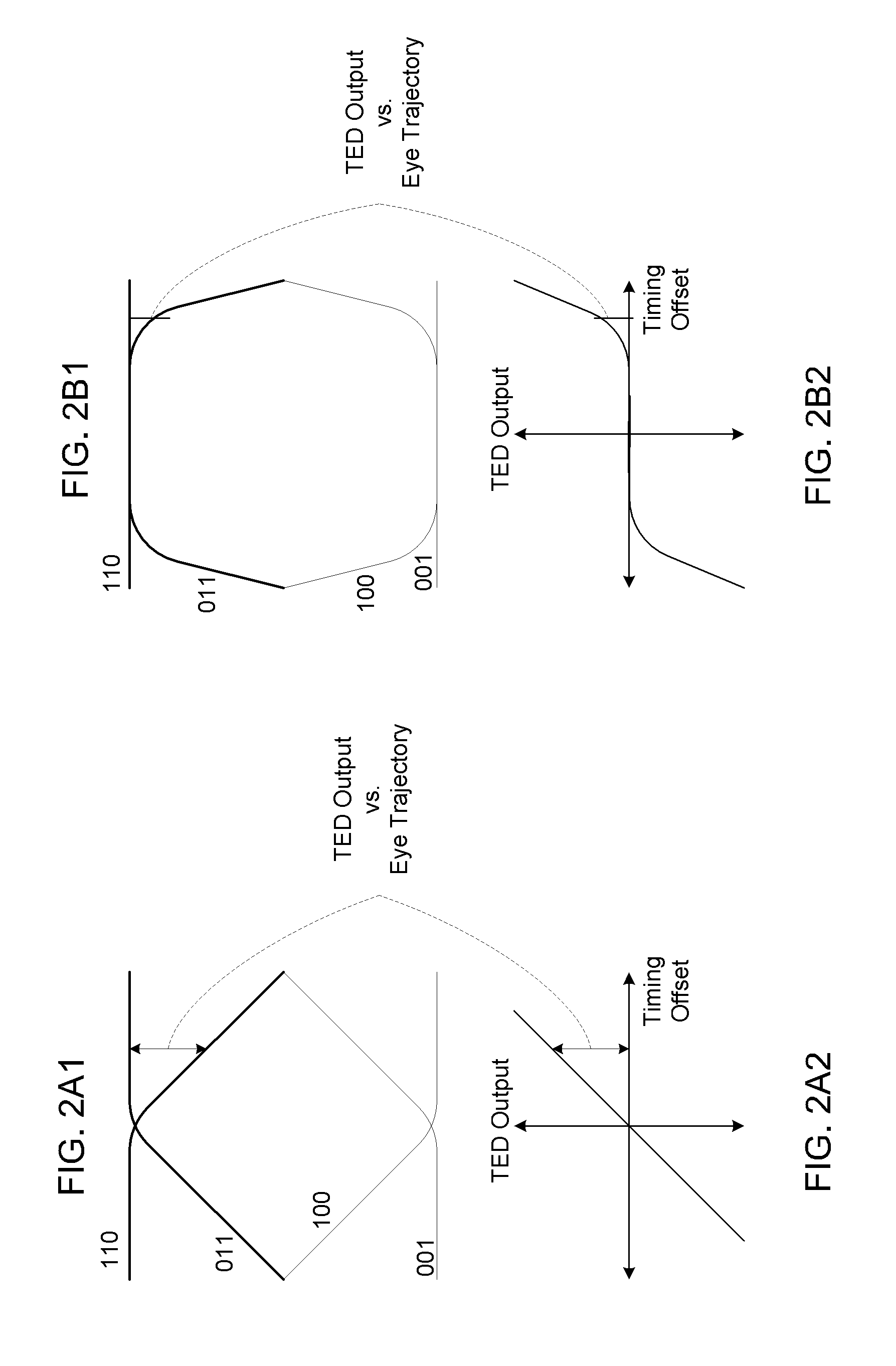
[0039]An alternative interpretation of the operation of a MM TED is possible. FIG. 2A1 illustrates a data eye and FIG. 2A2 illustrates a corresponding detector output for the case of re...


PUM


Abstract

Apparatus and methods calibrate and control detector gain in a Mueller-Muller timing detector. A Mueller-Muller circuit obtains timing information for a received signal in which the receiving device samples the signal once per baud period.

Description

CROSS-REFERENCE TO RELATED APPLICATION[0001]This application is a continuation application of U.S. application Ser. No. 13 / 549,030, filed Jul. 13, 2012, now U.S. Pat. No. 8,693,596, issued on Apr. 8, 2014, which claims the benefit under 35 U.S.C. §119(e) of U.S. Provisional Application No. 61 / 509,914, filed Jul. 20, 2011, the disclosures of each of which are hereby incorporated by reference in their entireties herein.[0002]This application is related to commonly-owned copending application titled “Parallel Replica CDR to Reduce or Minimize ADC and DSP Complexity,” having Ser. No. 13 / 549,104 filed on Jul. 13, 2012; to U.S. Provisional Application No. 61 / 507,435 filed Jul. 13, 2011; to commonly-owned copending application titled Parallel Replica CDR to Correct Offset and Gain in a Baud Rate Sampling Phase Detector, Ser. No. 13 / 549,134, filed on Jul. 13, 2012; and to U.S. Provisional Application No. 61 / 507,428, filed Jul. 13, 2011, also titled Parallel Replica CDR to Correct Offset and...

Claims


Application Information

Patent Timeline
Patent Type & Authority Patents(United States)
IPC IPC(8): H04L27/08H04B1/12H03G3/00
CPCH04B1/123H03G3/00H04L7/0062
Inventor WARNER, WILLIAM D.ZORTEA, ANTHONY EUGENE
Owner MICROSEMI STORAGE SOLUTIONS
Why Eureka
Try Eureka