Power tool, particularly a hand-held power tool

a power tool and hand-held technology, applied in the field of hand-held power tools, can solve the problems of reducing affecting the quality of work that can be achieved, so as to reduce the work to be performed by the user

Inactive Publication Date: 2015-07-07
ROBERT BOSCH GMBH
View PDF29 Cites 36 Cited by
  • Summary
  • Abstract
  • Description
  • Claims
  • Application Information

AI Technical Summary

Benefits of technology

[0011]The invention therefore also provides a method for operating a power tool, in particular a power tool of the aforementioned type, in the case of which the position of the detection area of a sensor system and, therefore indirectly the position of the power tool relative to a specified path are signalled. This is carried out in a manner that is easily recognized by a user, wherein the characteristic values detected using the sensor system are converted by the semi-autonomous guidance of the power tool into adjustment values for the tool, in particular for a saw blade, which orient the same relative to the specified path, and therefore, in conjunction with the approximate orientation performed by the user to the position of the detection surface relative to the specified path, precise machining is achieved along the specified path.
[0012]The detection area, which is large relative to a usually linear specified path, provides the user with the advantage of orientation on an area instead of on a line—which is usually difficult to as certain—as the specified path, and also makes it possible for a warning signal to be triggered and / or for the machine to be shut off if the user guides the power tool carelessly and displaces the detection area from the position thereof in which it overlaps the specified path, thereby ensuring, e.g. by the user becoming accustomed to the semi-autonomous operation, that inattentiveness and errors by the user as he guides the power tool do not result in damage to the work piece.
[0013]The invention is particularly advantageous for placing the power tool in the correct position on the particular work piece, that is, for making the first cut in the particular work piece at the point marked by the specified path. As the specified path, the detection area specifies a region in which the power tool need be displaced only transversely to the specified path, in particular needing only to be slid while lying on the work piece, until the rotational axis of the tool which lies in the center of the detection area—e.g. the saw blade of a jigsaw—cuts the marking line as the specified path. The user then merely needs to orient the power tool relative to the specified path. In the case of semi-autonomous operation of the power tool, in particular of the jigsaw, and setting the rotary position of the saw blade using an actuator system relative to the specified path, the orientation is implemented by specifying a corresponding rotary position, thereby ensuring that the user mainly only needs to provide support. Power tools that are operated using this assistance function, in particular jigsaws, therefore reduce the work to be performed by the user, even when starting work on a work piece, to primarily placing the machine such that the detection area overlaps the specified path, and then supporting the machine while the orientation relative to the specified path is performed by the machine.

Problems solved by technology

For users of such power tools, which are typically driven by an electric motor and are often used in practical applications as jigsaws or circular saws, the view of the particular processing point and a related specified path, which is indicated by a marking, in the region of the processing point is often greatly limited.
This negatively affects the quality of work that can be achieved.
Apart from the fact that auxiliary devices of that type are mechanically complex and are limited in terms of their possible uses, they must be adjusted.

Method used


Image

  • Power tool, particularly a hand-held power tool
  • Power tool, particularly a hand-held power tool
  • Power tool, particularly a hand-held power tool

Examples


Embodiment Construction

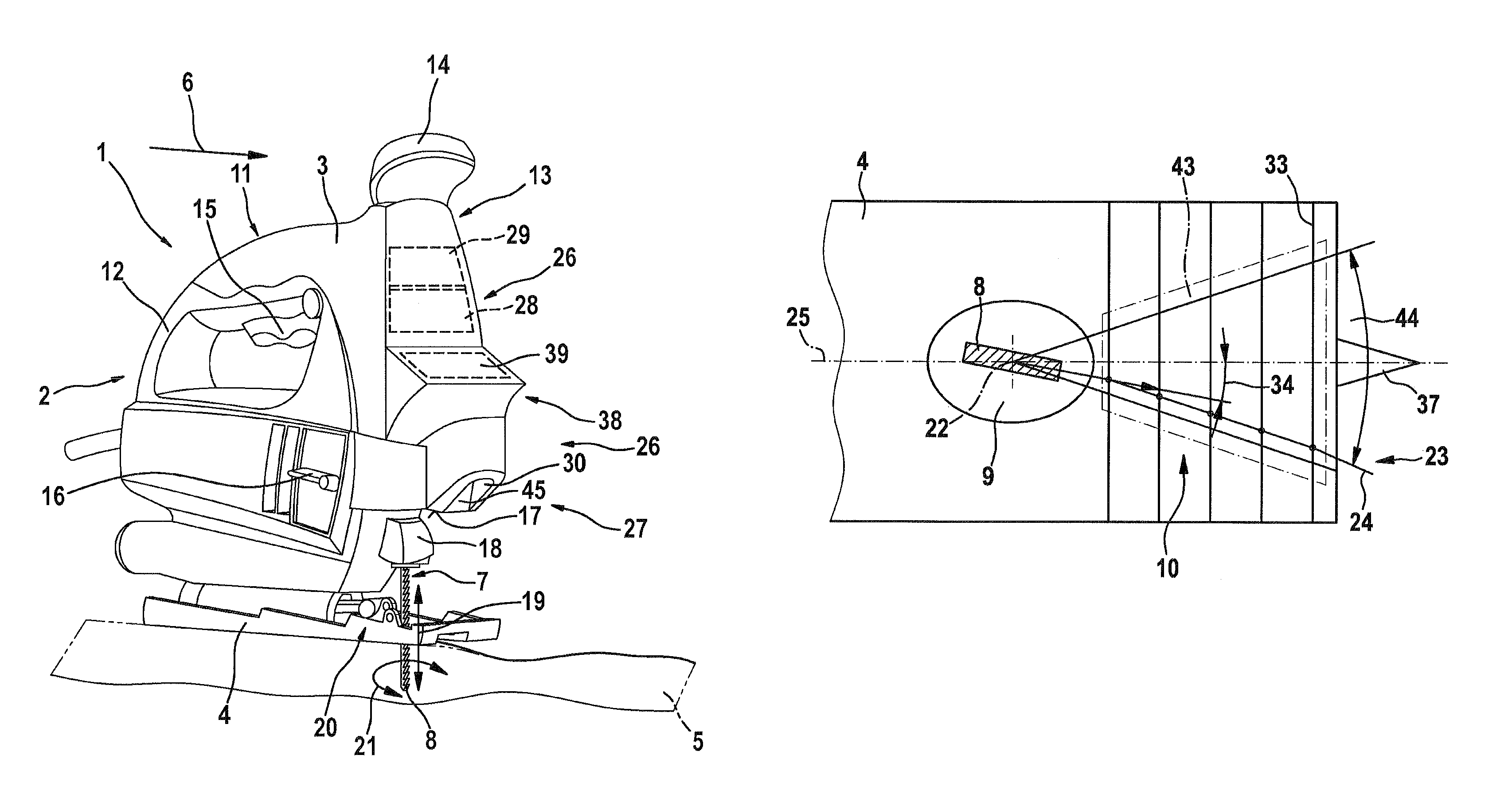
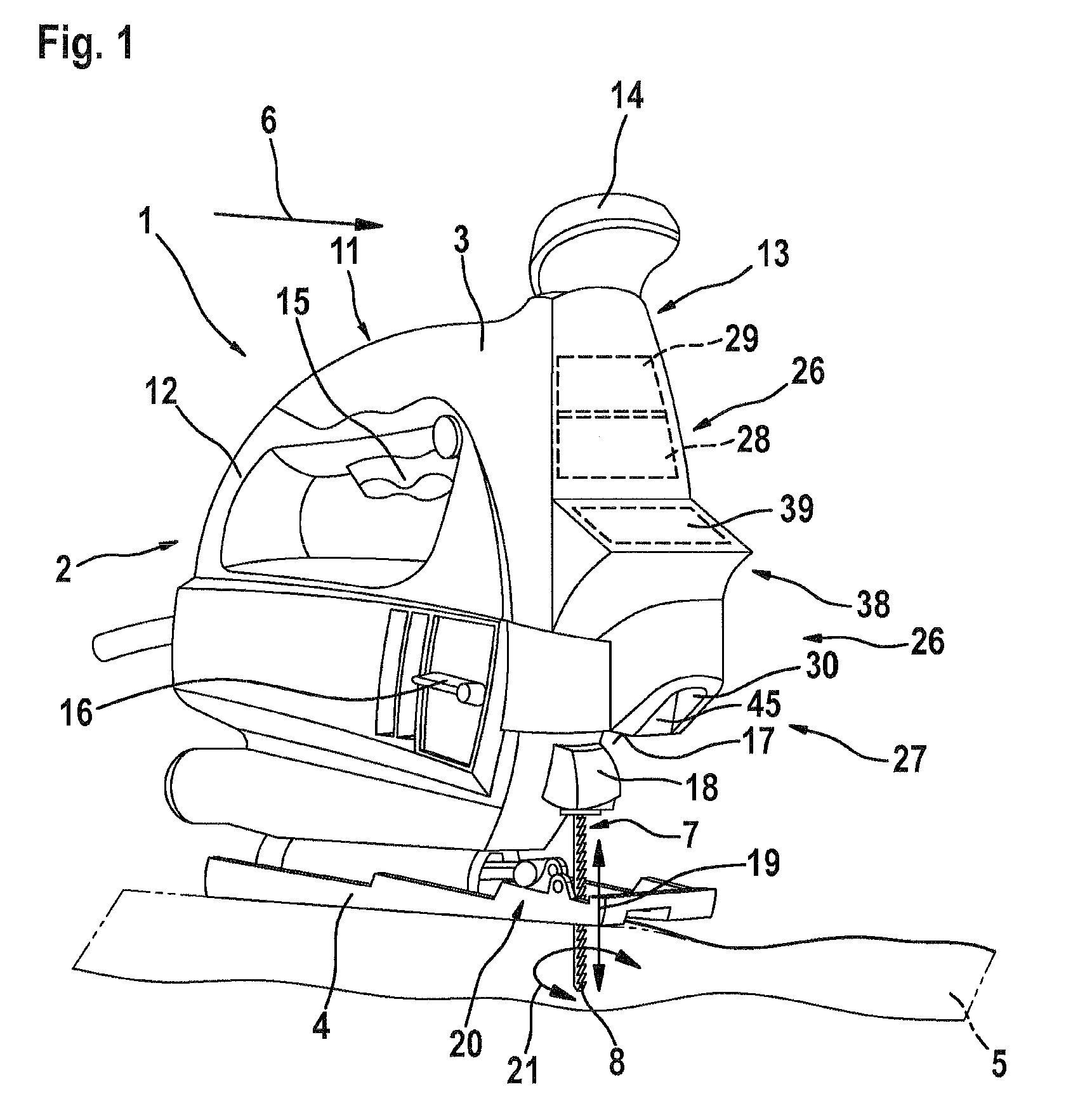
[0018]FIG. 1 shows, as an example of a power tool 1, a hand-held machine in the form of a jigsaw 2 that comprises a housing 3 and is supported on a work piece 5 by a base plate 4.

[0019]Jigsaw 2 comprises, in the front, relative to the working direction, a saw blade 8 as the working tool 7. In the working mode, it engages in work piece 5, on which jigsaw 2 is displaceably supported using base plate 4 thereof.

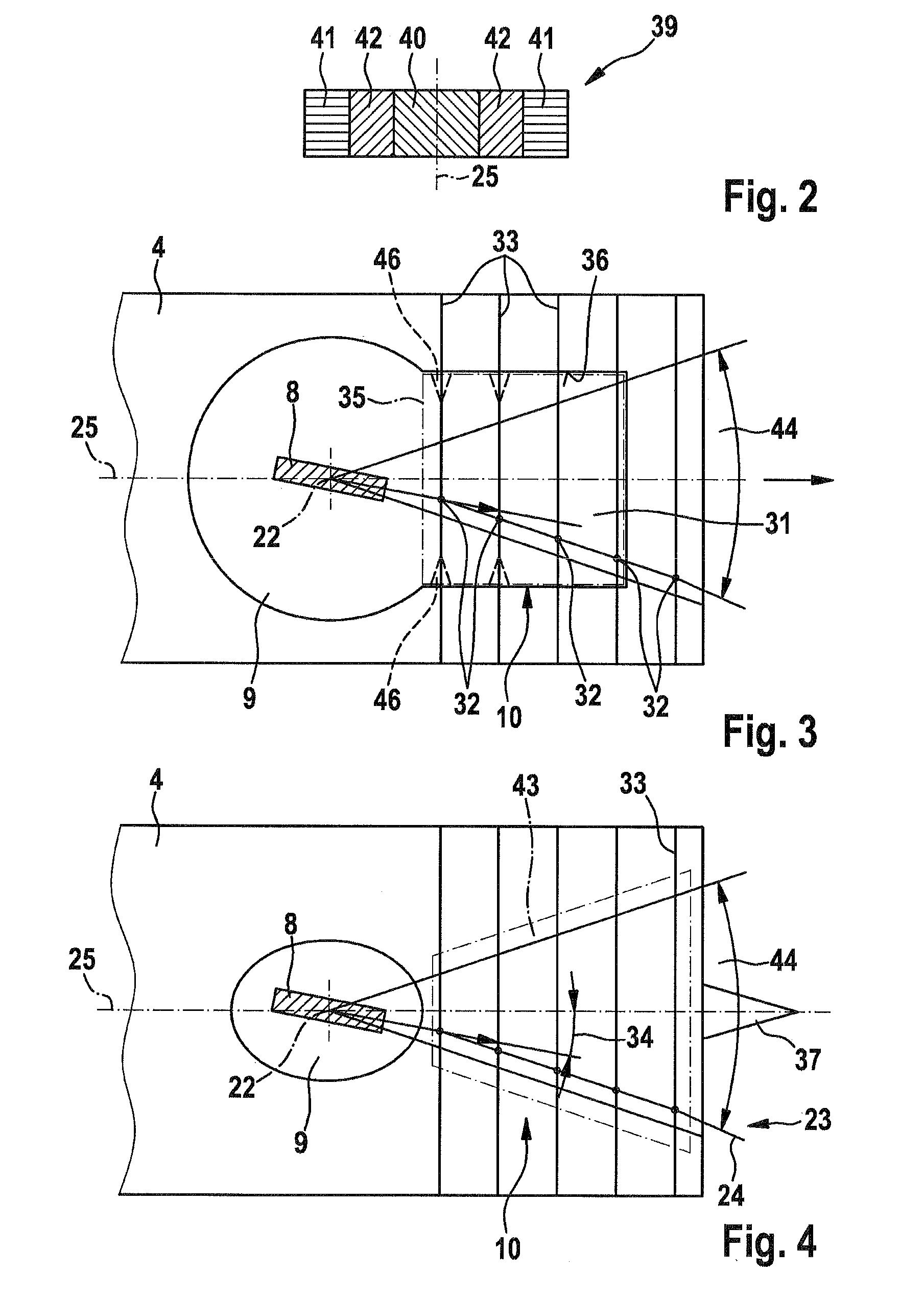
[0020]In the embodiment, jigsaw 2 is designed such that a viewing field 10 results for the user that preferably extends at least across the range of working region 9, which is determined by saw blade 8 and is illustrated in FIGS. 3 and 4 and, as shown, typically extends beyond working region 9 in working direction 6 to provide the user with the best possible overview of the working conditions, including those to come.

[0021]Housing 3 of jigsaw 2 is substantially conventional in design and comprises a U-shaped handle 11 which is disposed opposite—in the vertical direction—to base p...


PUM

PropertyMeasurementUnit
areaaaaaaaaaaa
coloraaaaaaaaaa
distanceaaaaaaaaaa

Abstract

The invention relates to a power tool (1), especially in the form of a hand-held jigsaw (2). In order to allow for a semi-autonomous operation which assists the user to guide the tool, the tool is provided with a sensor system (27) for observing a detection surface (31, 43) within which the desired working direction is detected as a path default (23) for the saw blade (8) serving as the tool (7) with respect to its alignment relative to the jigsaw (2), the detected path default being intended for downstream control means (26). Said control means align the saw blade (8) relative to the path default (23) by rotating it about its longitudinal axis (25) so that the user guiding the saw blade (2) only has to make sure that the path default (23) extends inside the detection surface (31, 43).

Description

CROSS-REFERENCE[0001]The invention described and claimed hereinbelow is also described in PCT / EP2009 / 053046, filed on Mar. 16, 2009 and DE 10 2008 001 757.4, filed on May 14, 2008. This German Patent Application, whose subject matter is incorporated here by reference, provides the basis for a claim of priority of invention under 35 U.S.C. 119 (a)-(d).[0002]The invention relates to a power tool, in particular a hand-held power tool.BACKGROUND INFORMATION[0003]For users of such power tools, which are typically driven by an electric motor and are often used in practical applications as jigsaws or circular saws, the view of the particular processing point and a related specified path, which is indicated by a marking, in the region of the processing point is often greatly limited. This negatively affects the quality of work that can be achieved. To prevent this, assistance systems in the form of auxiliary devices are used, which support guidance of the power tool in a manner oriented tow...

Claims


Application Information

Patent Timeline
Patent Type & Authority Patents(United States)
IPC IPC(8): B26D1/00B23D59/00B26D5/00B23D51/16B23D51/10
CPCB23D59/002B23D51/16B23D51/10
Inventor KOEDER, THILOPLATZER, JOACHIM
Owner ROBERT BOSCH GMBH
Why Eureka
Try Eureka