Method and device for regenerating a particle filter

a particle filter and regenerating technology, applied in mechanical equipment, machines/engines, electric control, etc., can solve problems such as the risk of damage to the particle filter, and achieve the effect of cost-effectiveness

Inactive Publication Date: 2015-07-14
ROBERT BOSCH GMBH
View PDF13 Cites 2 Cited by
  • Summary
  • Abstract
  • Description
  • Claims
  • Application Information

AI Technical Summary

Benefits of technology

[0015]It can be provided here that, by means of the presetting to a lambda value of λ<1, a lack of oxygen arises and the soot is oxidized via an endothermic heterogeneous water and gas equilibrium reaction (C+H2O←→CO+H2), and therefore the temperature loading in the particle filter can additionally be reduced. In this case, use can be made of the fact that, if there is a lack of oxygen, there is a change in the reaction kinetics for regenerating the particle filter. No additional oxygen is required here in the exhaust gas. Water is always present in the exhaust gas from combustion.
[0018]Since even the lean operation may cause an increased admission of oxygen to the particle filter, it is provided in a further variant of the method that, during or after the regeneration phase, lean operation with a lambda value of λ>1 is avoided for as long as critical conditions are present. Critical conditions include the exhaust gas temperature if the latter is lower than a limit value for the oxidation of soot, and the charging of the particle filter with soot if the quantity of soot is lower than a limit value.
[0019]A preferred use of the method, as described beforehand in terms of variant embodiments thereof, envisages the use for regenerating a particle filter close to the engine in the exhaust gas duct of an internal combustion engine which is embodied as a spark ignition engine and has suction-tube injection or direct injection. It is advantageous in this case that recourse can be made to existing lambda probes and to existing sensor concepts, since lambda probes are already provided in the exhaust gas duct of spark ignition engines for the lambda control, and therefore the signals of said lambda probes can be used at the same time for controlling the regeneration of the particle filter, as a result of which the method can be used particularly cost-effectively in future spark ignition engines having a particle filter.

Problems solved by technology

However, it has to be ensured by means of continuous monitoring that exothermy due to the burning of the soot does not become too large since otherwise there is the risk of damage to the particle filter.

Method used


Image

  • Method and device for regenerating a particle filter
  • Method and device for regenerating a particle filter

Examples


Embodiment Construction

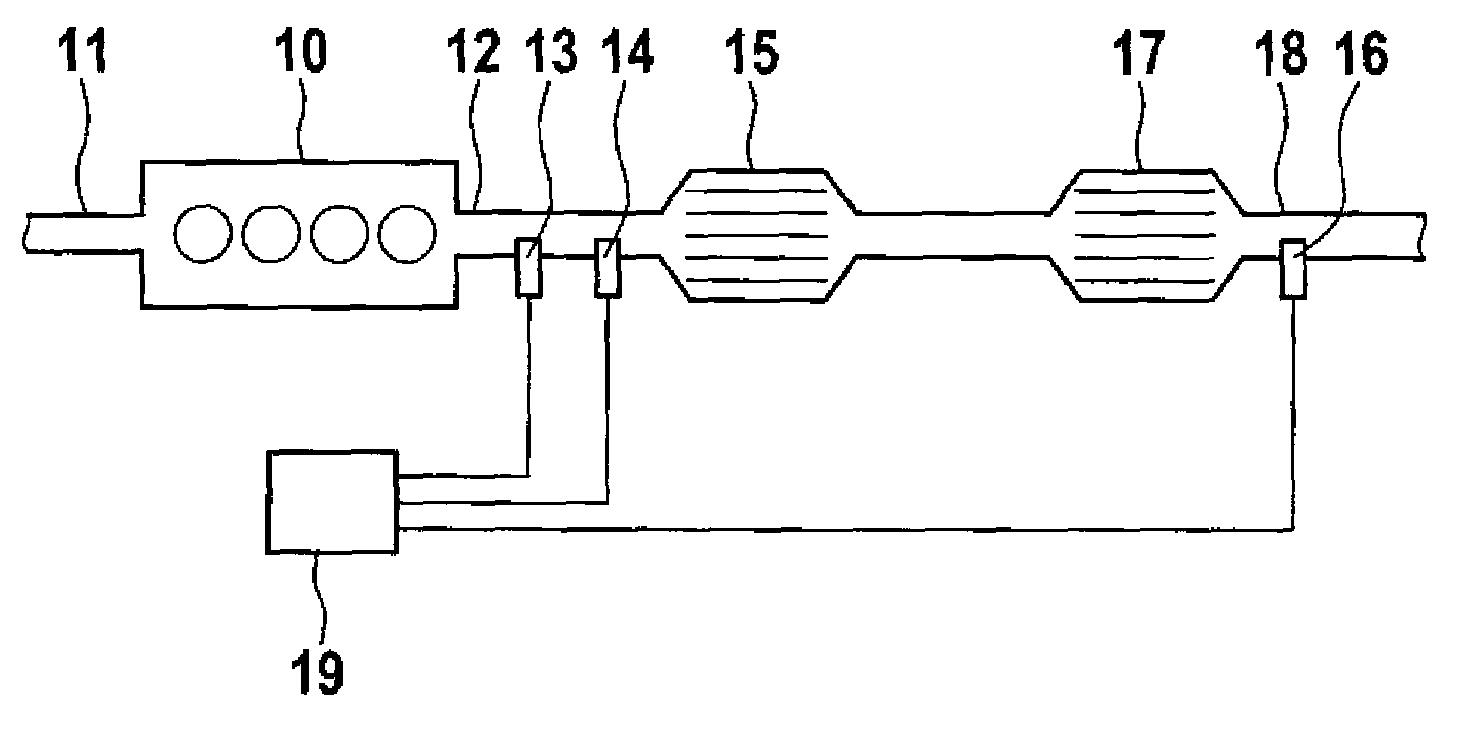
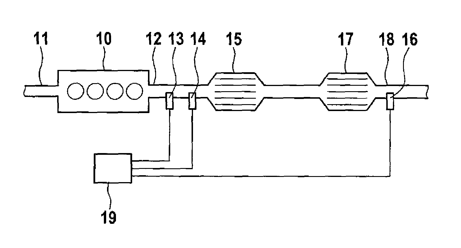
[0022]FIG. 1 shows an internal combustion engine 10 with an air supply 11 and a particle filter 15 arranged in an exhaust gas duct 12 and with a three-way catalytic converter 17 arranged downstream. The exhaust gas from the internal combustion engine 10, which exhaust gas is cleaned in the particle filter 15 and the three-way catalytic converter 17, is conducted away via an exhaust gas outlet 18. The lambda value of the exhaust gas in the exhaust gas duct 12 directly downstream of the internal combustion engine 10 is determined by means of a first lambda probe 13. In this region, the temperature of the exhaust gas is additionally determined by means of a temperature sensor 14. During operation of the internal combustion engine 10, particles are accumulated in the particle filter 15. This increase the exhaust gas counterpressure. The particle filter 15 therefore has to be burnt free when necessary and thus regenerated. Regeneration can take place only if the exhaust gas temperature i...


PUM


Abstract

A method and device for monitoring and controlling the regeneration of a particle filter in an exhaust gas duct of an internal combustion engine which has a three-way catalytic converter downstream of the particle filter, wherein the particle filter is regenerated by oxidative burning of the particles during a regeneration phase, wherein oxygen consumption is balanced, directly or indirectly, during the regeneration phase via the temporal variation of a first signal of a first lambda probe, which is arranged upstream of the particle filter, in comparison to the temporal variation of a second signal of a second lambda probe, which is arranged downstream of the particle filter. A lambda value of λ=1 is set downstream of the three-way catalytic converter during the regeneration of the particle filter by means of lambda control and the second lambda probe which is arranged downstream of the three-way catalytic converter.

Description

BACKGROUND OF THE INVENTION[0001]The invention relates to a method for monitoring and controlling the regeneration of a particle filter in an exhaust gas duct of an internal combustion engine which has a three-way catalytic converter downstream of the particle filter in the direction of flow of the exhaust gas, wherein the particle filter is regenerated by oxidative burning of the particles during a regeneration phase, wherein oxygen consumption is balanced, directly or indirectly, during the regeneration phase via the temporal variation of a first signal of a first lambda probe, which is arranged upstream of the particle filter in the exhaust gas direction, in comparison to the temporal variation of a second signal of a second lambda probe, which is arranged downstream of the particle filter in the exhaust gas direction.[0002]The invention furthermore relates to a device for carrying out the method according to the invention.[0003]In order to reduce the particle emission from diese...

Claims


Application Information

Patent Timeline
Patent Type & Authority Patents(United States)
IPC IPC(8): F01N3/00F01N3/10F02D41/02F02D41/14F01N13/00F01N3/035
CPCF01N3/101F01N13/009F02D41/029F02D41/0235F02D41/1441F02D41/1454F01N3/035Y02T10/22Y02T10/12
Inventor FRANK, MICHAELWINKLER, KLAUSKUFFERATH, ANDREASSTAVRIANOS, DIMITRIOS
Owner ROBERT BOSCH GMBH
Why Eureka
Try Eureka