Projection display for displaying an image to a viewer

Active Publication Date: 2015-07-14
BAE SYSTEMS PLC
View PDF28 Cites 66 Cited by
  • Summary
  • Abstract
  • Description
  • Claims
  • Application Information

AI Technical Summary

Benefits of technology

[0023]The image bearing light may be diffractively inputted into the first plate-like waveguide and diffractively outputted from the second plate-like waveguide and the diffractive input and diffractive output powers may be substantially matched. The diffractive input of the first or second plate-like waveguide and the diffractive output of the first

Problems solved by technology

Thus with these conventional displays the collimating optics used, that is the spherical lens system 1 and spherical exit lens system 4, are unnecessarily large and bulky, which is undesirable.
This means that the physical size of the conventional head up display as

Method used


Image

  • Projection display for displaying an image to a viewer
  • Projection display for displaying an image to a viewer
  • Projection display for displaying an image to a viewer

Examples


Embodiment Construction

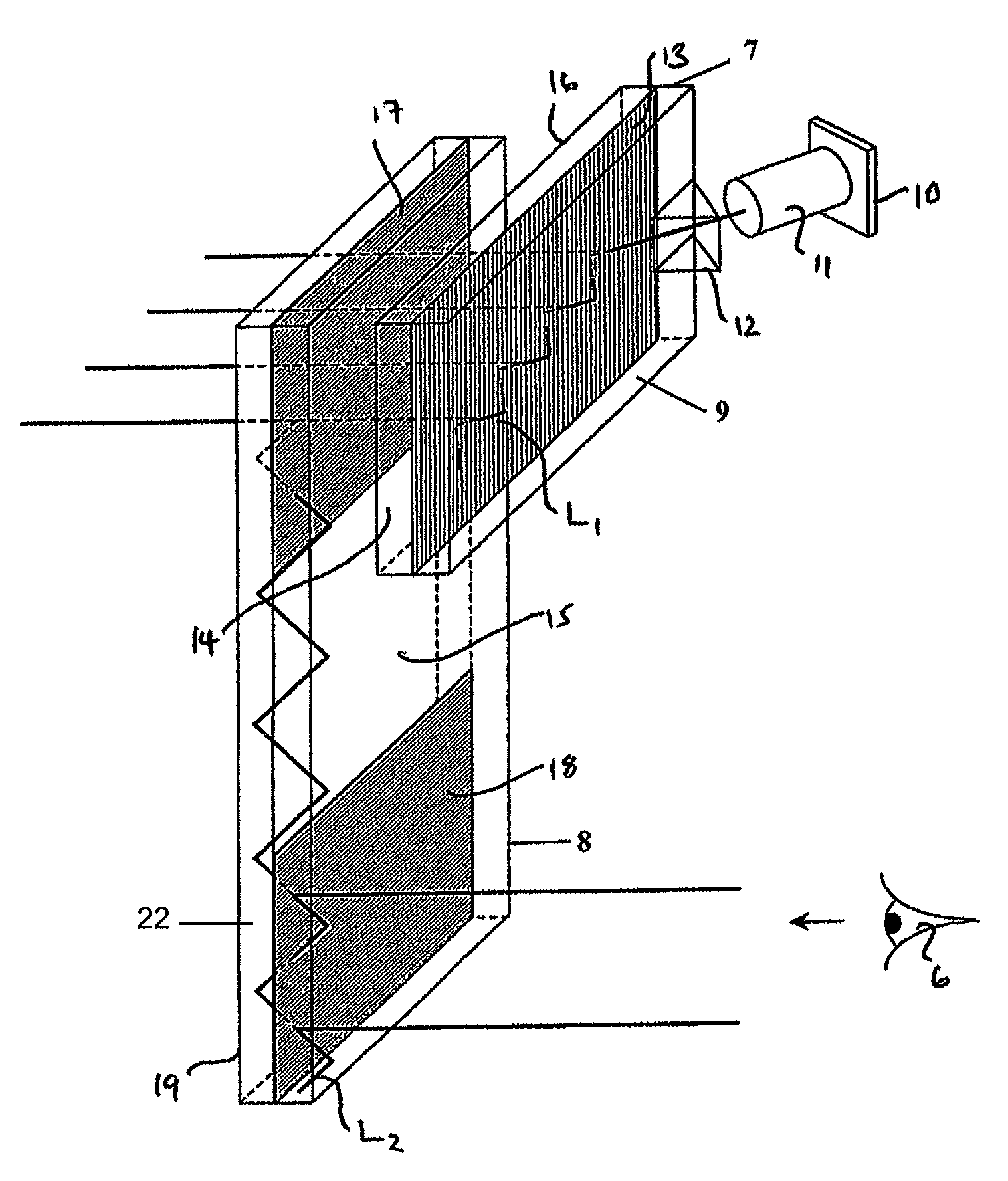
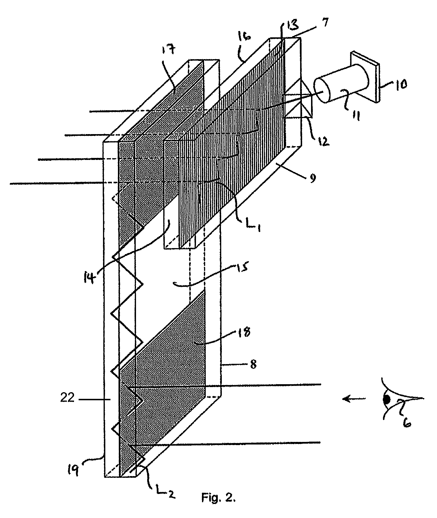
[0030]A projection display for displaying an image to a viewer 6 according to the invention as illustrated in FIGS. 2, 3 and 4 of the accompanying drawings in general uses waveguiding techniques to generate a collimated display subtending a large exit pupil at the point of a viewer 6 and a large field of view while using a small image-providing light source device. As illustrated, the projection display of the invention uses a first plate-like waveguide 7 made of light transmissive material such as glass or plastics and a second plate-like waveguide 8 made from a light transmissive and light transparent material such as glass or plastics.

[0031]In more detail, a projection display according to one aspect the present invention, as illustrated in FIG. 2, additionally includes an image-providing light source device located at a first face 9 of the first plate-like waveguide to inject image bearing light into the first plate-like waveguide 7 through the first face 9.

[0032]The image-provi...


PUM


Abstract

A projection display is provided including a first plate-like waveguide (7), an image providing light source device (10 and 11) located to inject image bearing light into the first plate-like waveguide 7. An input means (12) is provided on the waveguide (7) to reflect the image bearing light internally along the waveguide (7). A transmission grating (13) within the first plate-like waveguide (7) is provided to output image bearing light from the waveguide (7). A second plate-like waveguide (8) is located co-planar with the first plate-like waveguide (7) and has a coupling grating (17) therein to receive the image bearing light from the first plate-like waveguide (7). The second plate-like waveguide (8) also includes an exit grating (18) therein for diffracting the received image bearing light, diffracted by the coupling grating (17) out of the second plate-like waveguide (8) towards a viewer (6).

Description

CROSS-REFERENCE TO RELATED APPLICATIONS [0001]Not ApplicableSTATEMENT REGARDING FEDERALLY SPONSORED RESEARCH OR DEVELOPMENT [0002]Not ApplicableNAMES OF THE PARTIES TO A JOINT RESEARCH AGREEMENT[0003]Not ApplicableINCORPORATION-BY-REFERENCE OF MATERIAL SUBMITTED ON A COMPACT DISC[0004]Not ApplicableBACKGROUND OF THE INVENTION[0005]1. Field of the Invention[0006]This invention relates to a projection display for displaying an image to a viewer which is particularly, but not exclusively, suitable for use in a head up display, a helmet mounted display or a head mounted display.BACKGROUND OF THE INVENTION[0007]2. Description of Related Art[0008]Traditionally head up displays, which may be used in an aircraft, as shown in FIG. 1 of the accompanying drawings, use a convention spherical lens system 1 to generate a collimated display from an image provider such as a cathode ray tube 2. The light rays emanating from the spherical lens system 1 are reflected by a conventional fold mirror 3 th...

Claims


Application Information

Patent Timeline
IPC IPC(8): G03B21/14G02B27/42G02B27/00G02B27/01F21V8/00G02B6/00G02B5/30G02B5/18
CPCG02B27/0101G02B6/0028G02B6/0035G02B27/0081G02B27/0172G02B27/4211G02B5/18G02B5/30G02B6/00G02B6/0015G02B2027/015G02B2027/0118G02B2027/0125
Inventor SIMMONDS, MICHAEL DAVIDVALERA, MOHAMED SALIM
Owner BAE SYSTEMS PLC
Why Eureka
Try Eureka