
Wide-band multi stage Doherty power amplifier

a power amplifier and multi-stage technology, applied in the direction of rf amplifiers, high frequency amplifiers, transmission, etc., can solve the problems of limiting the available bandwidth for each service, low dc to rf conversion efficiency, and techniques typically come at the expense of amplifier sub-system efficiency, so as to achieve the same power rating and higher efficiency class

Active Publication Date: 2015-07-14
INTEL CORP
View PDF5 Cites 20 Cited by
  • Summary
  • Abstract
  • Description
  • Claims
  • Application Information

AI Technical Summary

Benefits of technology

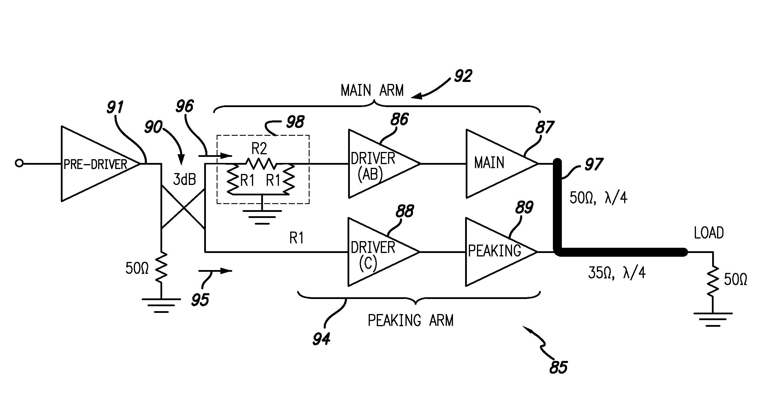
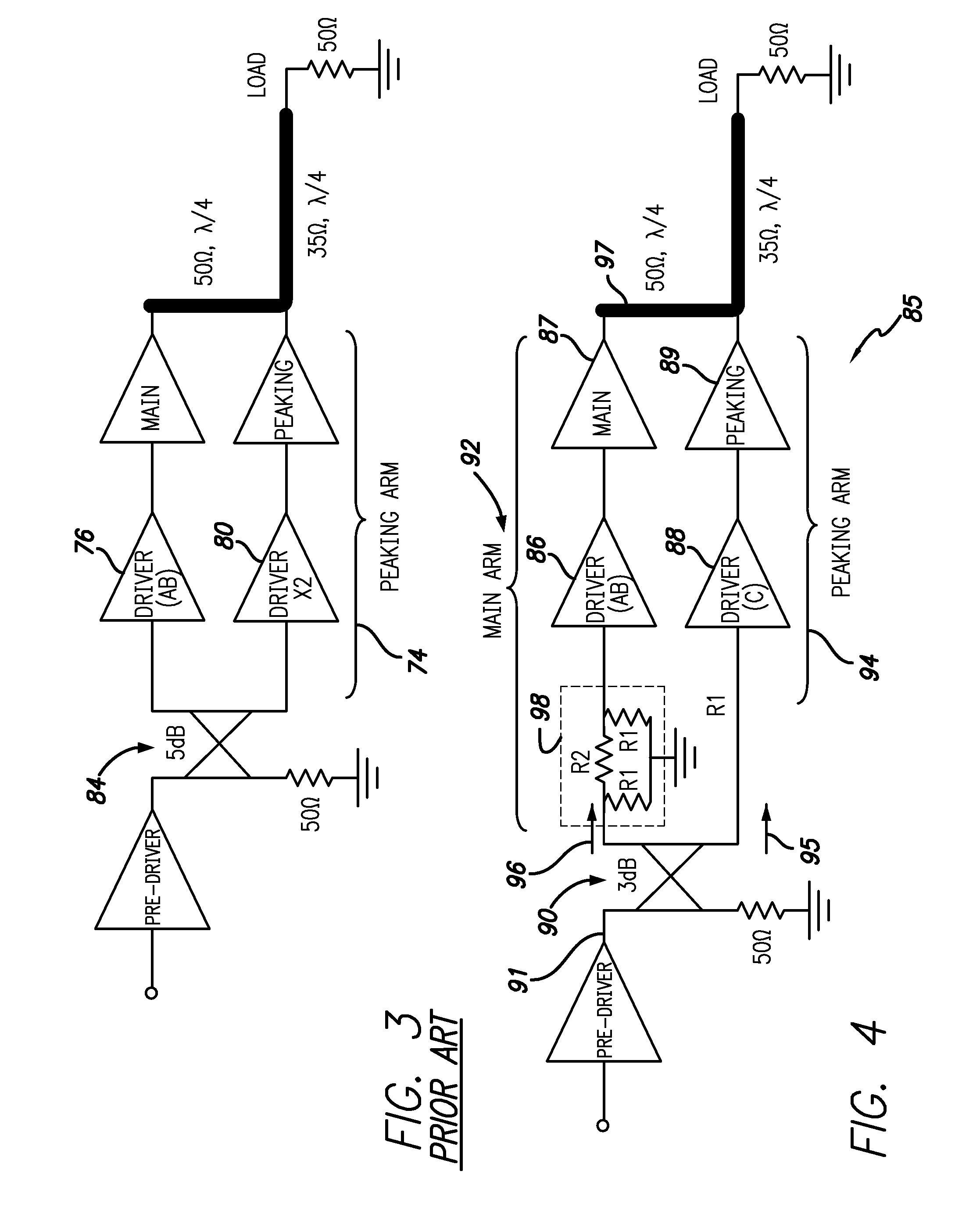
The present invention provides a power amplifier for RF signals that includes a main signal path and a peaking signal path, with a divider circuit for splitting the input signal into two equal power input signals. The main signal path has a main path driver amplifier and a main amplifier for amplifying the main signal, while the peaking signal path has a peaking path driver amplifier and a peaking amplifier for amplifying the peaking signal. The main amplifier has a higher power rating than the peaking path driver amplifier. The power amplifier also includes a quarter wave combiner circuit for combining the amplified signals and a method for amplifying the RF input signal. The technical effect of the invention is to provide a more efficient and effective power amplifier for RF signals.

Problems solved by technology

However, the commercial competition for access to bandwidth resources is also fierce which limits the available bandwidth for each service.
In such systems, to preserve modulation accuracy and prevent transmitter spurious emissions, the amplifying device has to maintain high linearity by having sufficient headroom for the signal peaks, albeit producing a modest average output power and therefore leading to low DC to RF conversion efficiency.
Nonetheless, despite the significant advances in linearization of RF power amplifiers, such techniques typically come at the expense of amplifier sub-system efficiency.
However, the approach outlined in the above referenced patent does not result to an optimum solution in two respects: cost and also performance over wide bandwidth.

Method used


Image

  • Wide-band multi stage Doherty power amplifier
  • Wide-band multi stage Doherty power amplifier
  • Wide-band multi stage Doherty power amplifier

Examples


Embodiment Construction

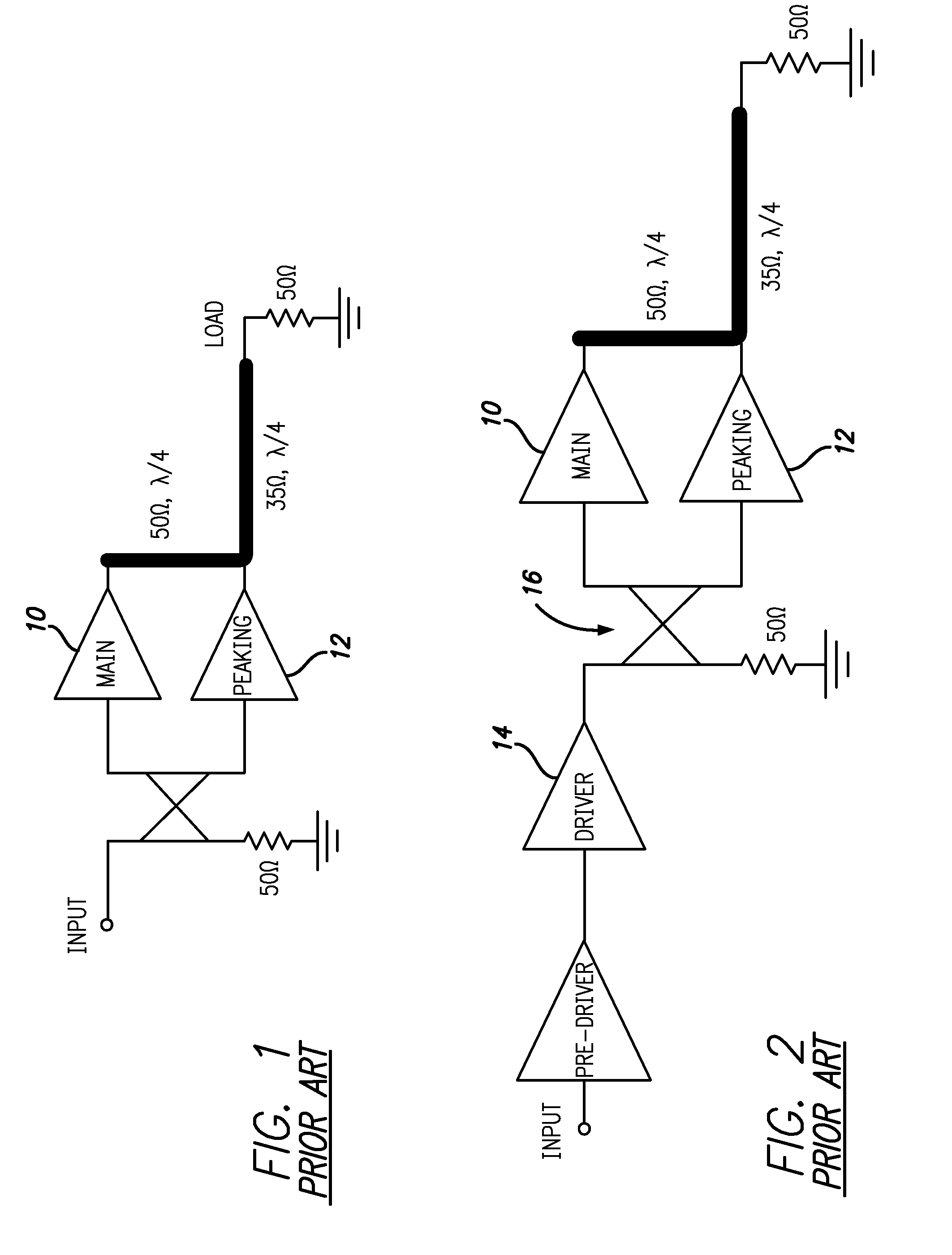
[0026]Embodiments of a power amplifier circuit configuration may achieve superior efficiency over broadband range frequencies using a multi-stage Doherty configuration. Conventional multi-stage Doherty amplifier configurations may offer potential for efficiency enhancement. However these configurations may suffer severe bandwidth limitation in practice and may have higher costs. Embodiments disclosed herein may alleviate such limitations. Embodiments of the amplifier topology and associated circuitry may achieve higher efficiency and smooth PA gain and phase characteristics over a 15% fractional bandwidth.

[0027]Teachings related to systems and methods employing power amplifiers disclosed in U.S. Pat. No. 7,362,170 to Louis dated Apr. 22, 2008 may be employed herein and the disclosure of which is incorporated herein by reference in its entirety. Distinctions between bias classes and the definitions of classes such as, but not limited to, class A, class B, class C, class AB, class BC ...


PUM


Abstract

A multi-stage Doherty power amplifier (“PA”) circuit which achieves superior efficiency over broadband range of frequencies is disclosed. Conventional multi-stage amplifiers may offer potential for efficiency enhancement but may suffer from cost penalties and severe bandwidth limitation in practice. Embodiments may employ a driver in the peaking arm which is biased in class C which may alleviate such limitations. The amplifier topology and associated circuitry described in embodiments may achieve high efficiency, smooth PA gain, and enhanced phase characteristics over a 15% fractional bandwidth with reduced costs.

Description

RELATED APPLICATION INFORMATION[0001]The present application claims priority under 35 U.S.C. Section 119(e) to U.S. Provisional Patent Application Ser. No. 61 / 450,093 filed Mar. 7, 2011, the disclosure of which is incorporated herein by reference in its entirety.BACKGROUND OF THE INVENTION[0002]1. Field of the Invention[0003]This present invention is related in general to high efficiency power amplifier systems and methods. More particularly, the invention is directed to systems and methods for power amplifiers exhibiting wide instantaneous signal bandwidth.[0004]2. Description of the Prior Art and Related Background Information[0005]The surge in wireless data traffic has continued over the past two decades and there is no evidence of a change in this trend. Given the propagation properties of the electromagnetic energy, for optimum coverage, carrier frequencies at lower frequency bands (i.e. from a fraction of a Giga Hertz to a few Giga Hertz) are preferred. However, the commercial...

Claims


Application Information

Patent Timeline
Patent Type & Authority Patents(United States)
IPC IPC(8): H01Q11/12H03F1/42H03F1/02
CPCH03F1/0288H03F1/42H03F2200/192H03F2200/408H03F3/19H03F3/211H03F2200/451H03F2203/21106
Inventor MASLENNIKOV, NIKOLAIKHANIFAR, AHMAD
Owner INTEL CORP
Learn More