Manufacturing method of optical fiber ribbon, and optical fiber ribbon manufactured by the manufacturing method

a manufacturing method and technology of optical fiber, applied in the direction of optics, fibre mechanical structures, instruments, etc., can solve the problems of optical fiber ribbon disadvantage in comparison, and achieve the effect of enhancing the slippage of the coating resin in the optical fiber

Active Publication Date: 2015-07-21
FUJIKURA LTD +1
View PDF13 Cites 28 Cited by
  • Summary
  • Abstract
  • Description
  • Claims
  • Application Information

AI Technical Summary

Benefits of technology

[0012]In accordance with the present invention, slippage of the coating resin in the optical fibers is enhanced in consideration of the Young's modulus of the resin, and accordingly, the coating resin can be suppressed from being shaved off in the event where the optical fibers are sent out from the coating dice.

Problems solved by technology

Therefore, in particular, in an optical fiber cable with a relatively small number of core wires (approximately several ten core wires to hundred core wires), for which requests for a density increase and a diameter reduction are increased, the optical fiber ribbon is disadvantage in comparison with an ultimate packaging form with regard to such a density increase and a diameter reduction as in a simple aggregate of single core wires.
However, in this case, there is an apprehension that, in the event of being sent out from the optical insertion holes, the optical fibers may be rubbed by outlet portions of the coating dice, and the resin coating on the optical fiber bare wires may be shaved off.

Method used


Image

  • Manufacturing method of optical fiber ribbon, and optical fiber ribbon manufactured by the manufacturing method
  • Manufacturing method of optical fiber ribbon, and optical fiber ribbon manufactured by the manufacturing method
  • Manufacturing method of optical fiber ribbon, and optical fiber ribbon manufactured by the manufacturing method

Examples


Embodiment Construction

[0017]A description is made of an embodiment of the present invention based on the drawings.

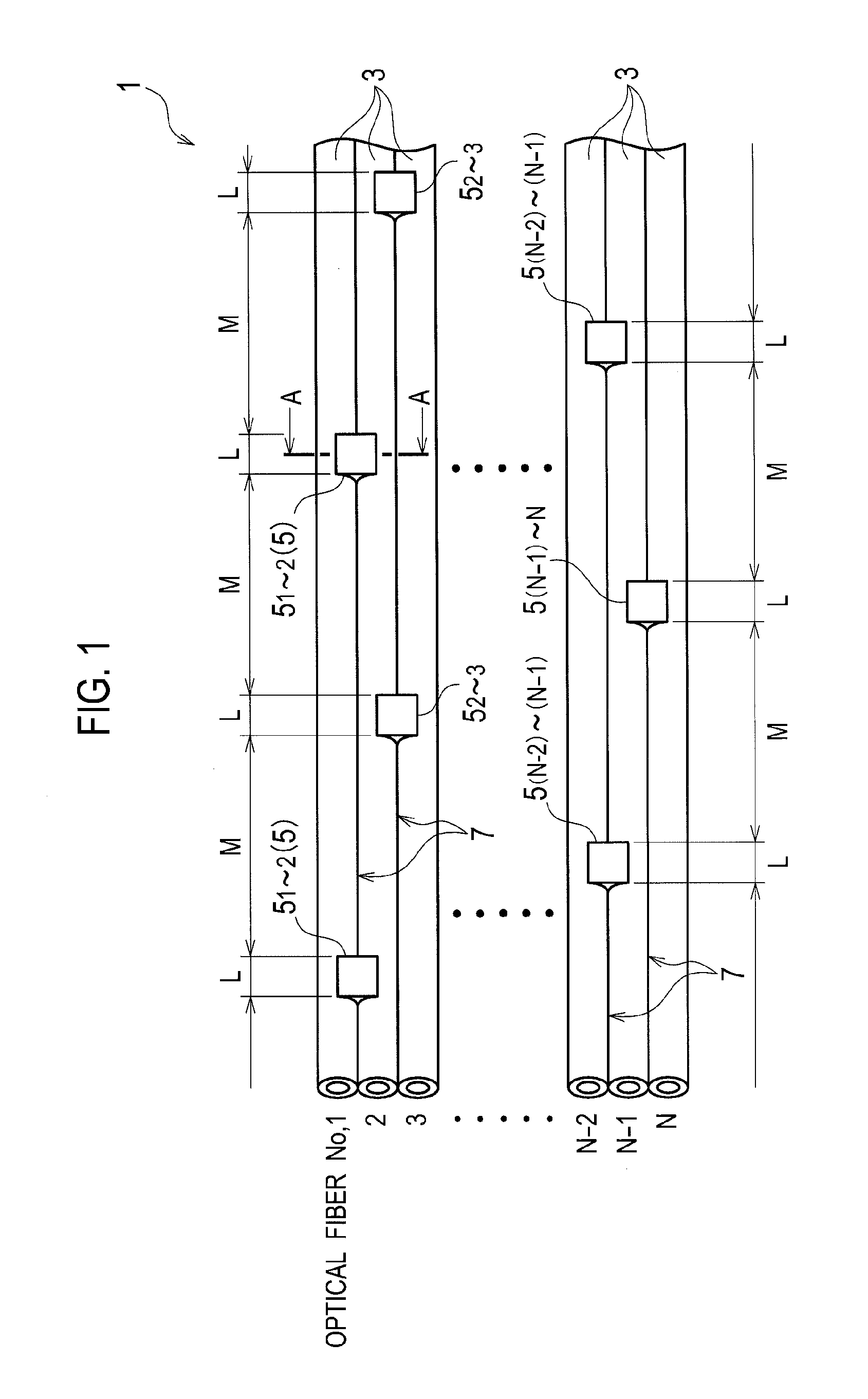
[0018]As shown in FIG. 1, an optical fiber ribbon (hereinafter, referred to as a ribbon) 1 of an optical fiber cable according to the embodiment of the present invention is configured in such a manner that a plurality of optical fibers 3 are arranged in parallel to one another, and here, is composed of the optical fibers 3 of which number is N in total. Among the N pieces of the optical fibers 3, two optical fibers 3 adjacent to each other are fixed to each other intermittently along a longitudinal direction of the optical fibers 3 concerned by adhered portions 5, each of which serves as a fixing portion for a plurality of spots. Portions between the adhered portions 5 provided in plural along the longitudinal direction are formed as separated portions 7 in which the optical fibers 3 are not adhered to each other.

[0019]In this event, adhered portions 51-2 between No. 1 and No. 2 of the optica...


PUM

PropertyMeasurementUnit
Young's modulusaaaaaaaaaa
friction forceaaaaaaaaaa
Young's modulusaaaaaaaaaa

Abstract

It is an object of the present invention to suppress a coating resin from being shaved off in an event where optical fibers are sent out from a coating dice. When a Young's modulus of ultraviolet curable resins 13 located on outermost layers of optical fibers 3 is 300 MPa or more, and the Young's modulus is 300 MPa to 600 MPa, a plurality of the optical fibers 3 in which friction force measured by the following measurement method is 0.3 N or less are arranged in parallel to one another, these respective optical fibers 3 are fixed to one another intermittently along a longitudinal direction thereof, and adhered portions 5 are formed.

Description

CROSS-REFERENCE TO RELATED APPLICATION[0001]The application is a Continuation of PCT Application No. PCT / JP2012 / 063617, filed on May 28, 2012, and claims the benefit of priority from the prior Japanese Patent Application No. 2011-125290, filed on Jun. 3, 2011, the entire contents of which are incorporated herein by reference.BACKGROUND OF THE INVENTION[0002]The present invention relates to a manufacturing method of an optical fiber ribbon, in which a plurality of optical fibers coated with a resin are arranged in parallel to one another, and these respective optical fibers are fixed to one another intermittently along a longitudinal direction thereof.[0003]An optical fiber ribbon for use in an optical fiber cable is one, in which an optical fiber strand or an optical fiber core wire is formed by coating outer circumferences of optical fiber bare wires (glass fibers) with a resin, a plurality of the optical fiber strands or the like are arranged in parallel to one another, and these ...

Claims


Application Information

Patent Timeline
Patent Type & Authority Patents(United States)
IPC IPC(8): G02B6/44
CPCG02B6/4403G02B6/44G02B6/448Y10T29/49826
Inventor NAMAZUE, AKIRATAKE, YUKIKOMATSUZAWA, TAKASHIOSATO, KENOKADA, NAOKIYAMADA, YUSUKE
Owner FUJIKURA LTD
Why Eureka
Try Eureka