Torsional vibration attenuation apparatus

a torsional vibration and attenuation apparatus technology, applied in the direction of vibration suppression adjustment, yielding coupling, coupling, etc., can solve the problems that the damping mechanism cannot sufficiently attenuate the torsional vibration at the deceleration time, and the torsional noise is generated by chinking noise, etc., to achieve simple construction, hysteresis torque, and simple

Inactive Publication Date: 2015-07-28
TOYOTA JIDOSHA KK
View PDF18 Cites 6 Cited by
  • Summary
  • Abstract
  • Description
  • Claims
  • Application Information

AI Technical Summary

Benefits of technology

[0048]The torsional vibration attenuation apparatus according to the present invention can be made simple in construction, and can make variable the positive side and the negative side hysteresis torques by the simple construction, and thereby can improve the workability of the production work for the torsional vibration attenuation apparatus, and can prevent the production cost of the torsional vibration attenuation apparatus from being increased.

Problems solved by technology

This type of a vehicle, however, encounters such a problem that muffled noises or chinking noises are generated by torsional vibrations originated from rotational fluctuations caused for example by torque fluctuations of an internal combustion engine.
The conventional damper mechanism is, however, constructed to have hysteresis torques at the acceleration time and at the deceleration time set at the same level, so that a damping mechanism can attenuate the torsional resonance of the drive train in the low rotational speed area at the acceleration time for the large hysteresis torque, but there is a possibility that the damping mechanism cannot sufficiently attenuate the torsional vibrations at the deceleration time.

Method used


Image

  • Torsional vibration attenuation apparatus
  • Torsional vibration attenuation apparatus
  • Torsional vibration attenuation apparatus

Examples


first embodiment

[0066]FIGS. 1 to 11 are views showing a first embodiment of the torsional vibration attenuation apparatus according to the present invention

[0067]First, the construction of the embodiment of the torsional vibration attenuation apparatus according to the present invention will be explained hereinafter.

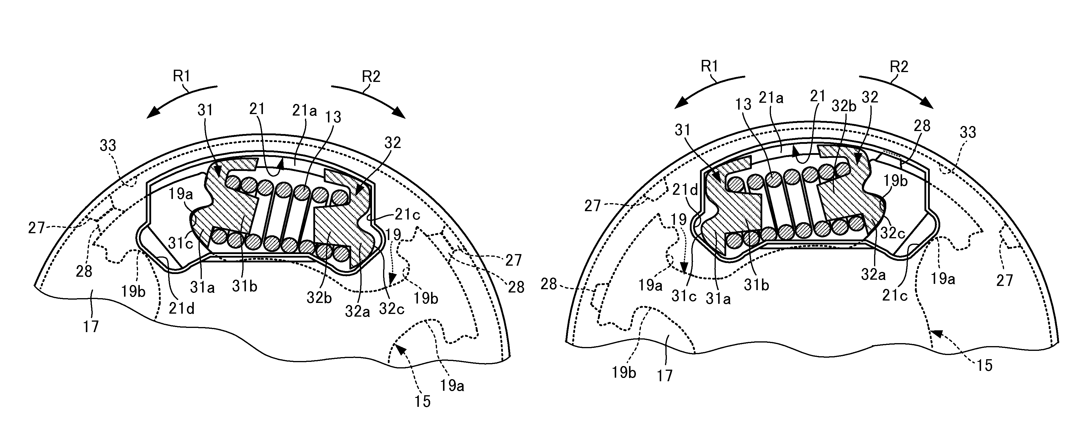
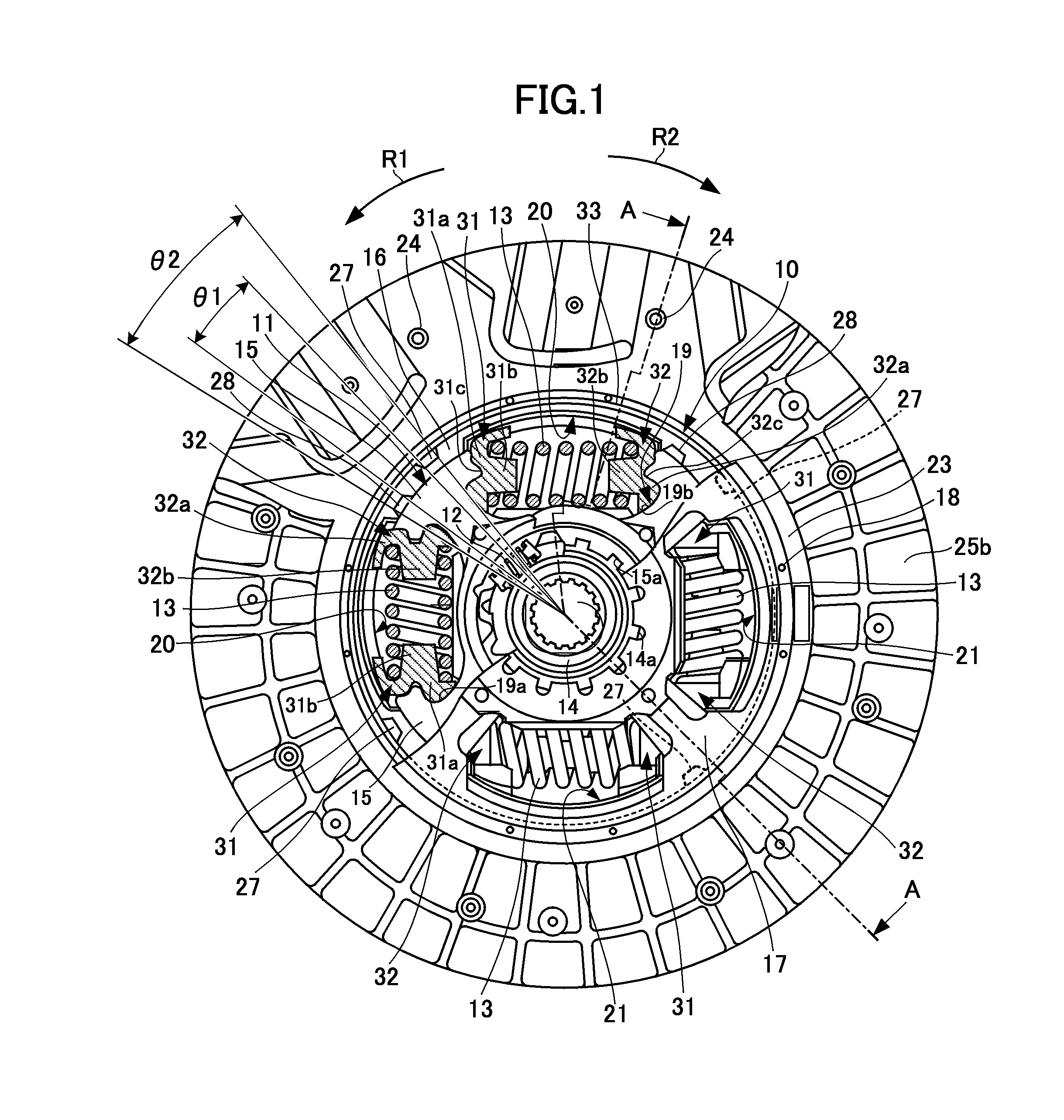
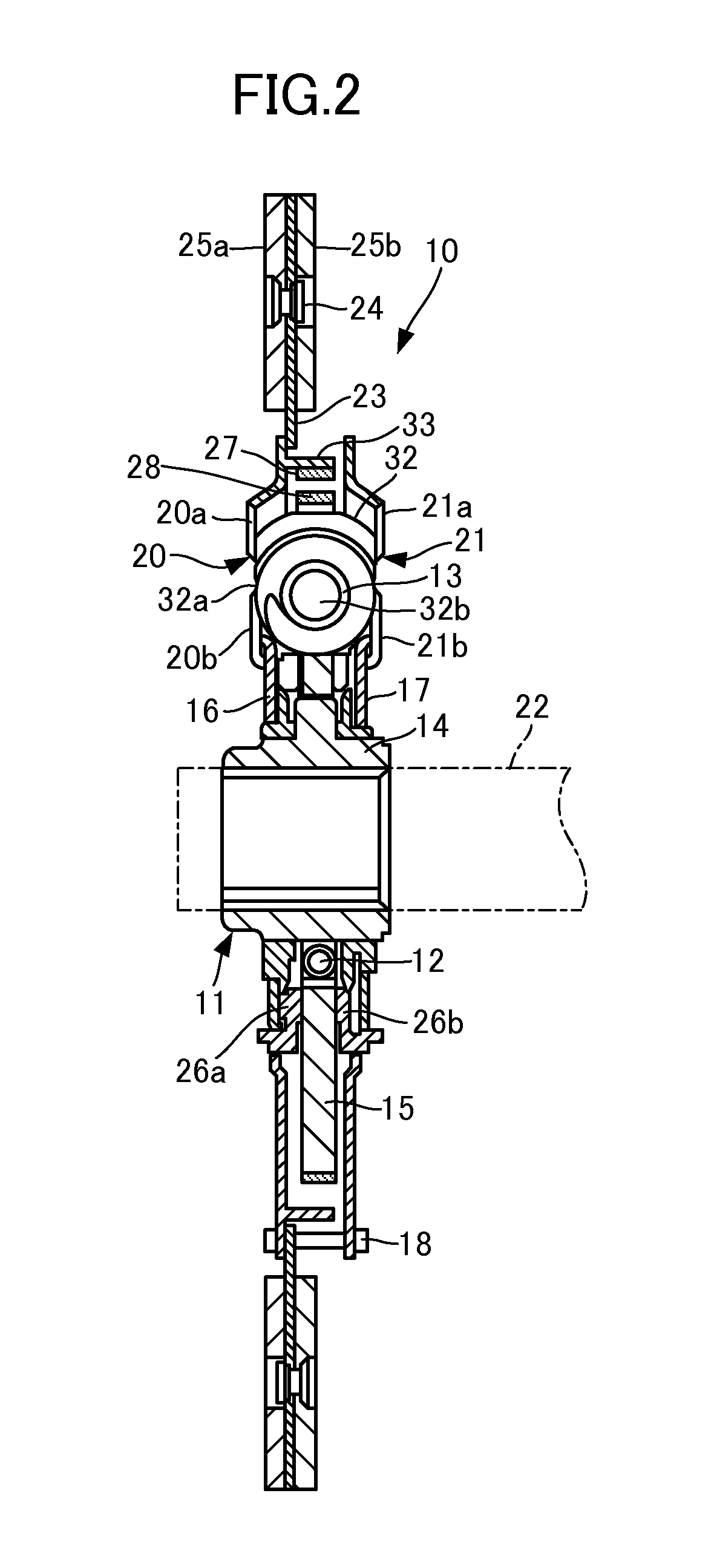
[0068]The torsional vibration attenuation apparatus 10 is shown in FIGS. 1 and 2 to comprise a hub member 11 constituting a second rotation member, disc plates 16, 17 coaxially disposed with the hub member 11, relatively rotatably disposed with respect to the hub member 11 and constituting a first rotation member, four coil springs 13 having the hub member 11 and the disc plates 16, 17 circumferentially resiliently connected with each other and constituting resilient members, and the spring seats 31, 32 having each of the coil springs 13 supported by the hub member 11.

[0069]The hub member 11 is constituted by a boss 14, and a flange 15 radially outwardly projecting from the boss 14. The...

second embodiment

[0150]FIGS. 12 to 16 are views showing a second embodiment of the torsional vibration attenuation apparatus according to the present invention. The explanation of the second embodiment of the torsional vibration attenuation apparatus will be omitted hereinafter with the constitutional elements and parts the same as those of the first embodiment of the torsional vibration attenuation apparatus bearing the same reference numerals of the first embodiment of the torsional vibration attenuation apparatus.

[0151]In FIGS. 12 to 14, the disc plate 16 is shown as being provided with a friction material 41 constituting the first friction material and extending a predetermined length in the circumferential direction of the first rotation member. The flange 15 of the hub member 11 is provided with a friction material 42 constituting the second friction material. The friction material 42 is disposed to face the friction material 41 in the axial direction of the hub member 11, and to be frictional...


PUM


Abstract

A torsional vibration damping device is configured to have hysteresis torques in the positive and negative sides varied by a simple construction, thereby improving the efficiency of production work and preventing an increase in production cost. Friction materials are respectively provided on surfaces of a hub member and the disc plates, the surfaces facing each other in the radial direction when the hub member is twisted in the positive side with respect to the disc plates. The friction materials are to be brought into friction contact with each other when the hub member is twisted by a specific angle with respect to the disc plates.

Description

CROSS REFERENCE TO RELATED APPLICATIONS[0001]This application is a National Stage of International Application No. PCT / JP2011 / 000640 filed Feb. 4, 2011, the contents of all of which are incorporated herein by reference in their entirety.TECHNICAL FIELD[0002]The present invention relates to a torsional vibration attenuation apparatus, and more particularly to a torsional vibration attenuation apparatus which comprises a first rotation member and a second rotation member intervening between an internal combustion engine and a drive train, in which the first rotation member and the second rotation member are relatively rotatably connected with each other through a resilient member, so that a rotational torque is transmitted between the first rotation member and the second rotation member.BACKGROUND ART[0003]There has so far been known a drive source such as an internal combustion engine, an electric motor and the like drivably connected with wheels through a drive train including a tra...

Claims


Application Information

Patent Timeline
Patent Type & Authority Patents(United States)
IPC IPC(8): F16F15/129F16D3/12F16F15/123
CPCF16D3/12F16F15/129F16F15/12333
Inventor TAKENAKA, TETSUHIRO
Owner TOYOTA JIDOSHA KK
Why Eureka
Try Eureka