Circuit arrangement and method for monitoring electrical isolation

a technology of circuit arrangement and electrical isolation, applied in the direction of short-circuit testing, resistance/reactance/impedence, measurement of impedence, etc., can solve problems such as the diagnosis of electrical isolation

Active Publication Date: 2015-07-28
ROBERT BOSCH GMBH
View PDF14 Cites 0 Cited by
  • Summary
  • Abstract
  • Description
  • Claims
  • Application Information

AI Technical Summary

Benefits of technology

[0005]The circuit arrangement according to the invention has the advantage over the known circuit arrangements that it is inexpensive and has a robust design and also that it enables the detection of a fault in the electrical isolation, in particular also so-called symmetrical faults, even during operation of the power supply system, or the motor vehicle. The circuit arrangement according to the invention is characterized by the fact that in each case at least one variable resistor is connected between the connections and ground, and by the fact that a voltage measuring device for detecting a potential shift of the ground relative to the supply voltage when at least one of the resistors is varied and an drive direction, which determines the ability of the electrical isolation to function depending on the detected potential shift, are provided. Therefore, in each case one variable resistor is connected between each of the connections of the high-voltage system and ground, which variable resistor or the resistance value thereof can be varied, as required. The voltage measuring device detects a relative potential shift between ground and the connections or the supply voltage potentials present in each case at the connections in the form of voltages, in particular output voltages, when at least one of the resistors is varied. By virtue of the resistors being varied, a potential shift to be expected results when the electrical isolation is functioning properly. An evaluation device which is preferably provided determines whether the electrical isolation is functioning properly depending on the detected potential shift, in particular by a comparison with a potential shift to be expected. If the detected potential shift deviates from the potential shift to be expected or deviates from this to too great an extent, a fault in the electrical isolation is diagnosed by the evaluation device. If appropriate, the evaluation device then introduces countermeasures or safety measures, such as disconnection of the system, for example. In order to achieve a meaningful result, the voltage present between the connections of the high-voltage system needs to be assumed to be known. Since the bias voltage system is generally connected to a corresponding energy source, the voltage can either be predicted or detected using simple measurement means.
[0006]Preferably, the variable resistors are each in the form of measuring resistors with a fixedly predetermined resistance value and an associated actuable switch for connecting or isolating the respective measuring resistor. Instead of providing expensive measuring resistors with a variable resistance value, the invention merely provides for the connection or isolation of the measuring resistors, as a result of which a particularly simple and inexpensive possibility for varying a resistance and for detecting the potential shifts is provided.
[0014]Preferably, the monitoring of the electrical isolation is repeated continuously, in particular also during operation of the power supply system of the motor vehicle, in particular hybrid motor vehicle, with the result that continuous checking of the electrical isolation takes place.

Problems solved by technology

If the detected potential shift deviates from the potential shift to be expected or deviates from this to too great an extent, a fault in the electrical isolation is diagnosed by the evaluation device.

Method used


Image

  • Circuit arrangement and method for monitoring electrical isolation
  • Circuit arrangement and method for monitoring electrical isolation
  • Circuit arrangement and method for monitoring electrical isolation

Examples


Embodiment Construction

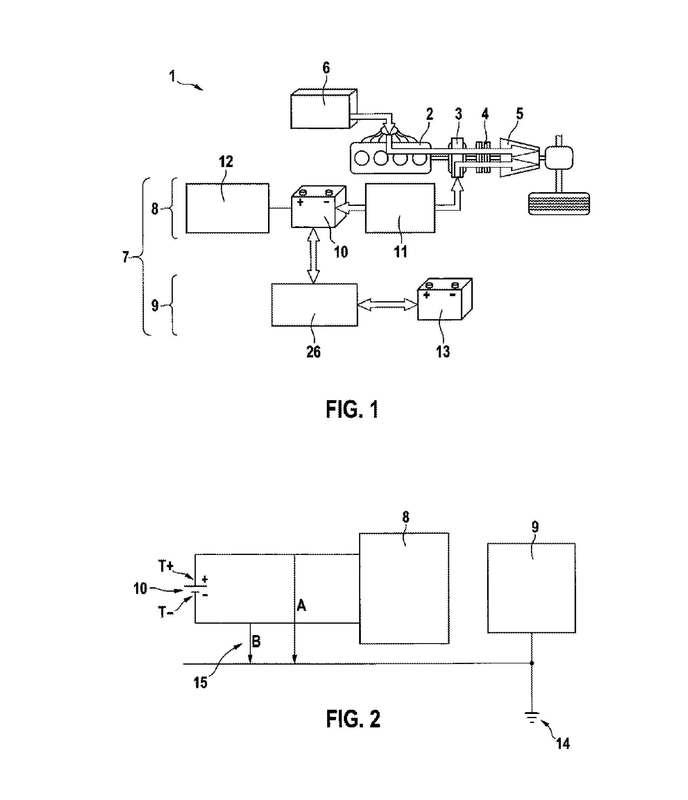
[0021]FIG. 1 shows a simplified illustration of a hybrid drive apparatus 1 of a motor vehicle (only indicated here). The hybrid drive apparatus 1 has a conventional internal combustion engine 2, the output shaft of which is connected to an electric machine 3. The electric machine 3 can in turn be operatively connected via an actuable clutch 4 to a transmission 5, the output shaft of which is connected to driving wheels of the motor vehicle.

[0022]While the internal combustion engine 2 is supplied with fuel from a fuel tank 6, the electric machine 3 is connected to a power supply system 7 of the vehicle. The power supply system 7 is divided into a high-voltage system 8 and a low-voltage system 9. In this case, the high-voltage system 8 is connected to the electric machine 3 and has an electrical energy store 10, which is connected to the electric machine 3 via an inverter 11. In this case, an energy management system 12 is associated with the energy store 10, said energy management sy...


PUM


Abstract

A circuit arrangement (16) for monitoring electrical isolation in a power supply system (7). Electrical isolation is provided between a high-voltage system (8) and a low-voltage system (9), wherein the high-voltage system (8) and the low-voltage system (9) are connected to ground (14), and wherein the high-voltage system (8) has a first connection (T+) for a first supply voltage potential and a second connection (T−) for a second supply voltage potential of a voltage source (10). In each case, at least one variable resistor (Rm1, Rm2) is connected between the connections (T+, T−) and ground (14), and a voltage measuring device (17) for detecting a potential shift of the ground (14) relative to the supply voltage potentials when at least one of the resistors (Rm1, Rm2) is varied. And an evaluation device, which determines the ability of the electrical isolation to function depending on the detected potential shifts.

Description

BACKGROUND OF THE INVENTION[0001]The invention relates to a circuit arrangement for monitoring electrical isolation in a power supply system, in particular a motor vehicle, which electrical isolation is provided between a high-voltage system and a low-voltage system of the power supply system, wherein the high-voltage system and the low-voltage system are connected to ground, and wherein the high-voltage system has a first connection for a first supply voltage potential and a second connection for a second supply voltage potential of a voltage source.[0002]In addition, the invention relates to a method for monitoring electrical isolation in a power supply system as has been described above.[0003]Circuit arrangements and methods for monitoring electrical isolation are known from the prior art. In particular in the case of modern motor vehicles which have a so-called hybrid drive apparatus, the on-board power supply system comprises at least two subsystems, a high-voltage system which...

Claims


Application Information

Patent Timeline
Patent Type & Authority Patents(United States)
IPC IPC(8): G01R31/08G01R27/02G01R31/02G01R27/16G01R31/00
CPCG01R27/02G01R31/025G01R27/16G01R31/006G01R31/52
Inventor PEUSER, THOMAS
Owner ROBERT BOSCH GMBH
Why Eureka
Try Eureka