Paraplegia prevention stent graft

a stent and paraplegia technology, applied in the field of medical devices, can solve the problems of blood supply immediately after, and it is difficult to cannulate an upward-facing renal artery, and achieve the effect of reducing the chances of paraplegia

Active Publication Date: 2015-08-04
COOK MEDICAL TECH LLC
View PDF119 Cites 19 Cited by
  • Summary
  • Abstract
  • Description
  • Claims
  • Application Information

AI Technical Summary

Benefits of technology

[0010]The one or more branches left open in this embodiment are allowed for a time to perfuse the aneurysm to reduce the chances of paraplegia, and are subsequently blocked. A preferred location of an upward facing branch is slightly more anterior and facing slightly to the left, to make targeting an upward-facing renal artery more workable.

Problems solved by technology

There can be a problem, however, of blood supply immediately after an operation, at least in part relating to blood pressure.
It may be difficult to cannulate an upward-facing renal artery, as tracking a stiff bridging stent out of the branch and into the artery may pull the wire out of the branch.

Method used


Image

  • Paraplegia prevention stent graft
  • Paraplegia prevention stent graft
  • Paraplegia prevention stent graft

Examples


Embodiment Construction

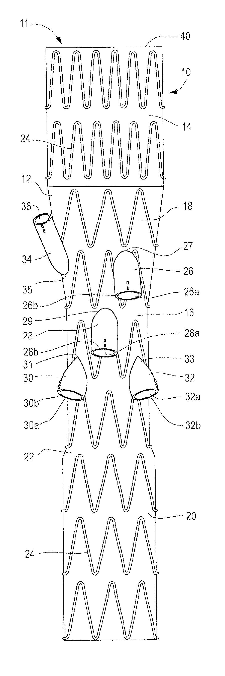
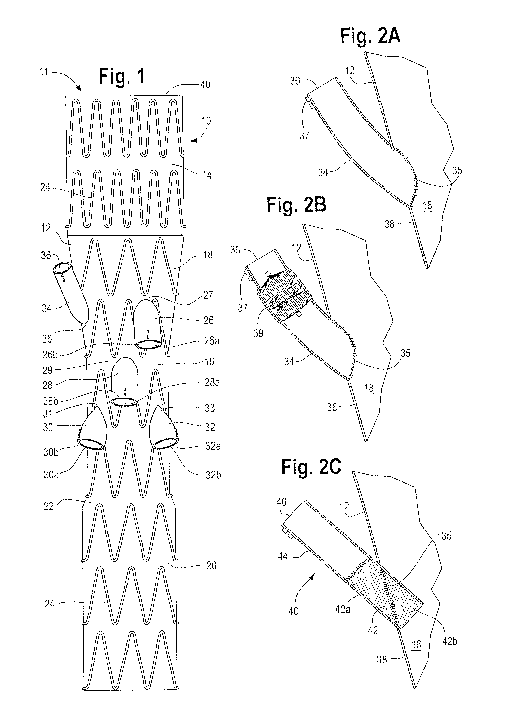
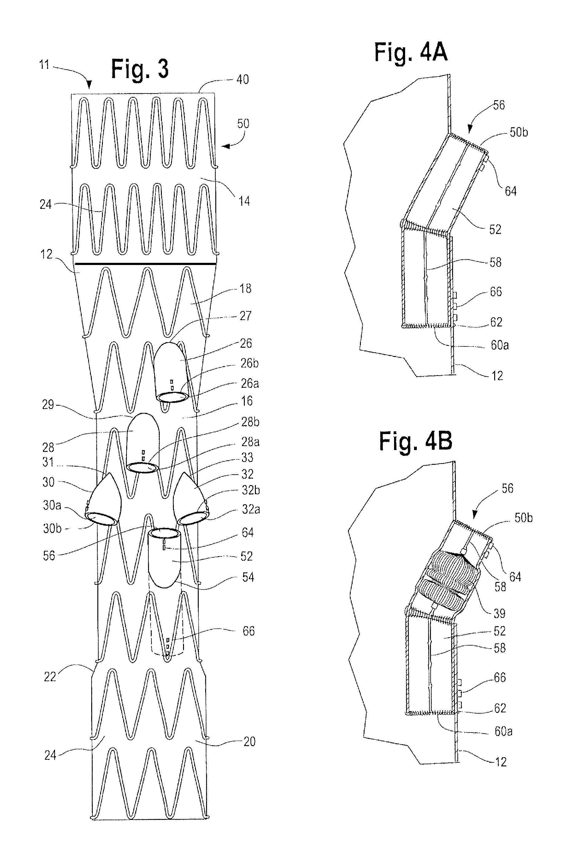
[0025]Now looking at the FIGS. 1, 2A and 2B of the drawings, a stent graft 10 according to one embodiment of the invention is shown that comprises a tubular body 12 of a biocompatible graft material. The tubular body 12 has a main lumen 11 therethrough. The tubular body 12 comprises a proximal portion 14 of a selected diameter and a reduced diameter portion 16, distal of the proximal portion 14, having a diameter which is less than the selected diameter. The tubular body 12 also has a proximal tapered portion 18 extending between the proximal portion 14 and the reduced diameter portion 16. The tubular body 12 may also comprise a distal portion 20, distal of the reduced diameter portion 16, which distal portion 20 has a diameter that is less than the selected diameter of the proximal portion 14, and that is greater than the diameter of the reduced diameter portion 16; and a distal tapered portion 22 extending between reduced diameter portion 16 and the distal portion 20. In this embo...


PUM


Abstract

A stent graft for deployment into the aorta of a patient has a tubular body with a proximal portion of a selected diameter; preferably a reduced diameter portion, distal of the proximal portion, having a diameter less than the selected diameter; a tapered portion, extending between the proximal portion and the reduced diameter portion; and optionally a distal portion, distal of the reduced diameter portion. At least three, preferably four or five, low profile side arms are provided, preferably in the reduced diameter portion and / or the tapered portion, for connection of an arm extension to an aortic branch vessel. All but one of the side arms are to be connected at the physician's choice, depending on the anatomy of the patient. One side arm is to provide temporary perfusion to external of the stent graft after deployment of the stent graft into the aorta, and is subsequently blocked.

Description

RELATED APPLICATIONS[0001]This is a continuation-in-part of U.S. patent application Ser. No. 13 / 502,001, which is a 35 USC 371 application from PCT Application No. PCT / US2010 / 052446, filed Oct. 13, 2010, and has a 35 USC 371(c) date of May 16, 2012, and which claims the benefit of priority to U.S. Provisional Application No. 61 / 278,814, filed Oct. 13, 2009; and this is also a continuation-in-part of U.S. patent application Ser. No. 13 / 457,092, filed Apr. 26, 2012, which claims the benefit of priority of U.S. Provisional Application No. 61 / 480,091, filed Apr. 28, 2011; and the benefit of priority of U.S. Provisional Application No. 61 / 526,061, filed Aug. 22, 2011; and the benefit of priority of U.S. Provisional Application No. 61 / 581,475, filed Dec. 29, 2011, the disclosures of all of which are incorporated by reference herein.FIELD OF INVENTION[0002]This invention relates to a medical device and more particularly to an implantable endovascular device, such as a stent graft for deplo...

Claims


Application Information

Patent Timeline
Patent Type & Authority Patents(United States)
IPC IPC(8): A61F2/07A61F2/82A61F2/95A61F2/06A61F2/89
CPCA61F2/82A61F2/95A61F2/07A61F2002/061A61F2250/006A61F2/89A61F2002/075A61F2220/005A61F2220/0075A61F2250/0039
Inventor IVANCEV, KRASNODARROEDER, BLAYNE A
Owner COOK MEDICAL TECH LLC
Why Eureka
Try Eureka