Crossover valve in double piston cycle engine

a cross-over valve and cycle engine technology, applied in combustion engines, machines/engines, gas engines, etc., can solve the problems of thermal waste in conventional internal combustion engines, the single cylinder cannot be optimized both, and the fuel efficiency of conventional internal combustion engines is low, so as to achieve efficient and reliable transfer of working fluids

Active Publication Date: 2015-08-04
TOUR ENGINE INC
View PDF24 Cites 3 Cited by
  • Summary
  • Abstract
  • Description
  • Claims
  • Application Information

AI Technical Summary

Benefits of technology

[0014]In view of the foregoing disadvantages inherent in the known types of internal combustion engine now present in the prior art, embodiments of the present invention include a DPCE combustion engine utilizing temperature differentiated cylinders that converts fuel into energy or work in a more efficient manner than conventional internal combustion engines. Some embodiments of the present invention utilize novel valves for facilitating efficient and reliable transfer of working fluid from a DPCE's compression chamber to combustion chamber.

Problems solved by technology

However, a single cylinder cannot be optimized both as a compressor (requires cold environment for optimal efficiency performance) and a combustor (requires hot environment and optimal expansion of the working fluid for optimal efficiency performance) at the same time and space.
Conventional internal combustion engines have low fuel efficiency—more than one half of the potential thermal energy created by conventional engines is estimated to dissipate through the engine structure and exhaust outlet, without adding any useful mechanical work.
A major cause of thermal waste in conventional internal combustion engines is the essential cooling system (e.g., radiator), which alone dissipates heat at a greater rate and quantity than the total heat actually transformed into useful work.
Furthermore, conventional internal combustion engines are able to increase efficiencies only to a low degree by employing low heat rejection methods in the cylinders and pistons.
Further inefficiency results from high-temperature in the cylinder during the intake and compression strokes.
This high temperature reduces engine volumetric efficiency, makes the piston work harder and, hence, reduces efficiency during these strokes.
Moreover, conventional means to make the engine expansion ratio larger than the compression ratio (Miller and Atkinson cycles, for example) are less efficient than the increase in efficiency, which is possible if all four strokes would have not been executed in a single cylinder.
Another problem with conventional internal combustion engines is an incomplete chemical combustion process, which reduces efficiency and causes harmful exhaust emissions.
However, these references fail to disclose how to differentiate cylinder temperatures to effectively isolate the firing (power) cylinders from the compression cylinders and from the surrounding environment.
In addition, these references fail to disclose how to minimize mutual temperature influence between the cylinders and the surrounding environment.
Further, these references fail to disclose engine improvements that enhance conventional internal combustion engine efficiency and performance by raising the power cylinder temperature and lowering the compression cylinder temperature.
However, elevated temperatures in the entire Thomas engine reside not only throughout the combustion and exhaust strokes, but also during part of the compression stroke.

Method used


Image

  • Crossover valve in double piston cycle engine
  • Crossover valve in double piston cycle engine
  • Crossover valve in double piston cycle engine

Examples


Embodiment Construction

[0130]The invention is described in detail below with reference to the figures, wherein similar elements are referenced with similar numerals throughout. It is understood that the figures are not necessarily drawn to scale. Nor do they necessarily show all the details of the various exemplary embodiments illustrated. Rather, they merely show certain features and elements to provide an enabling description of the exemplary embodiments of the invention.

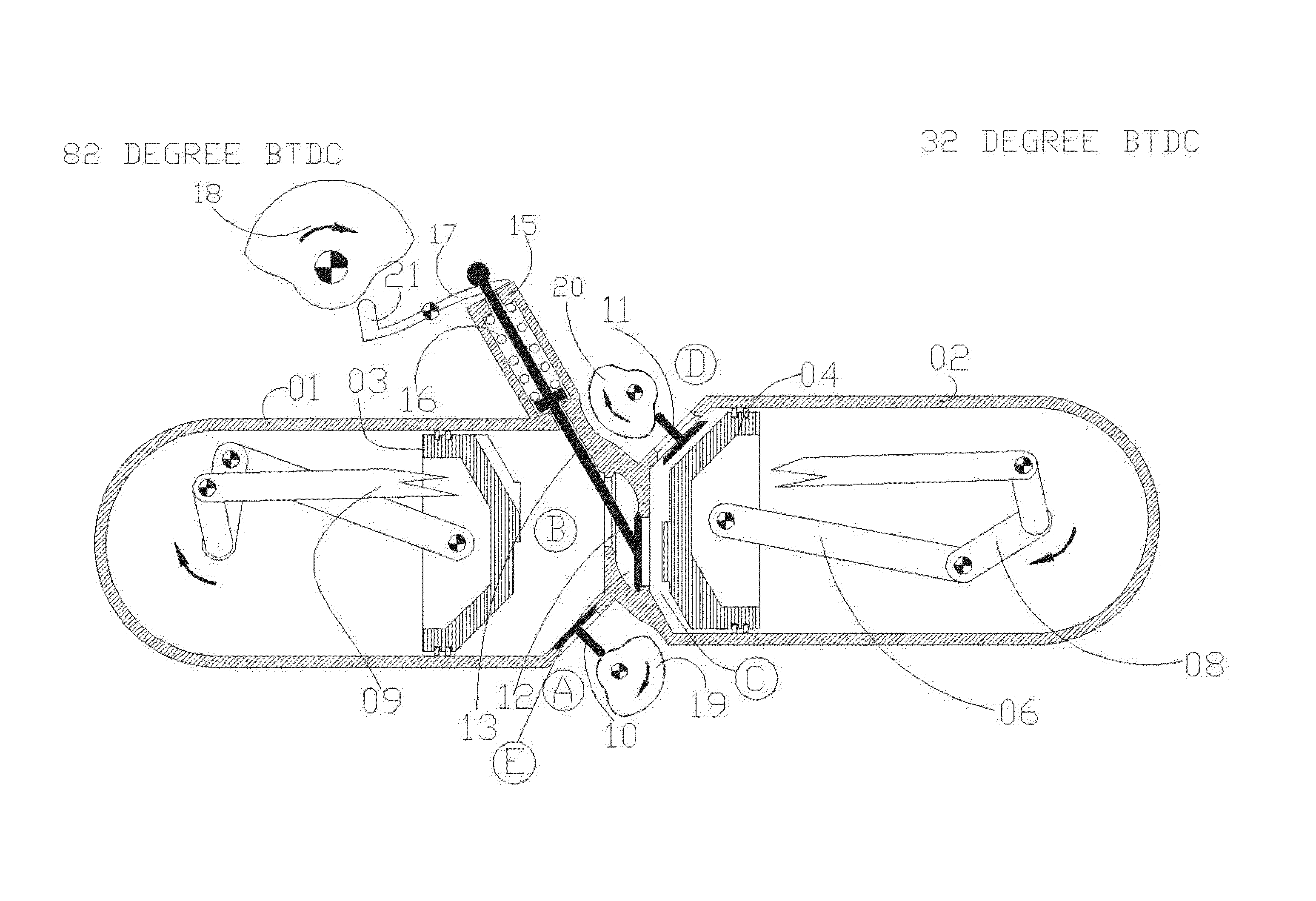
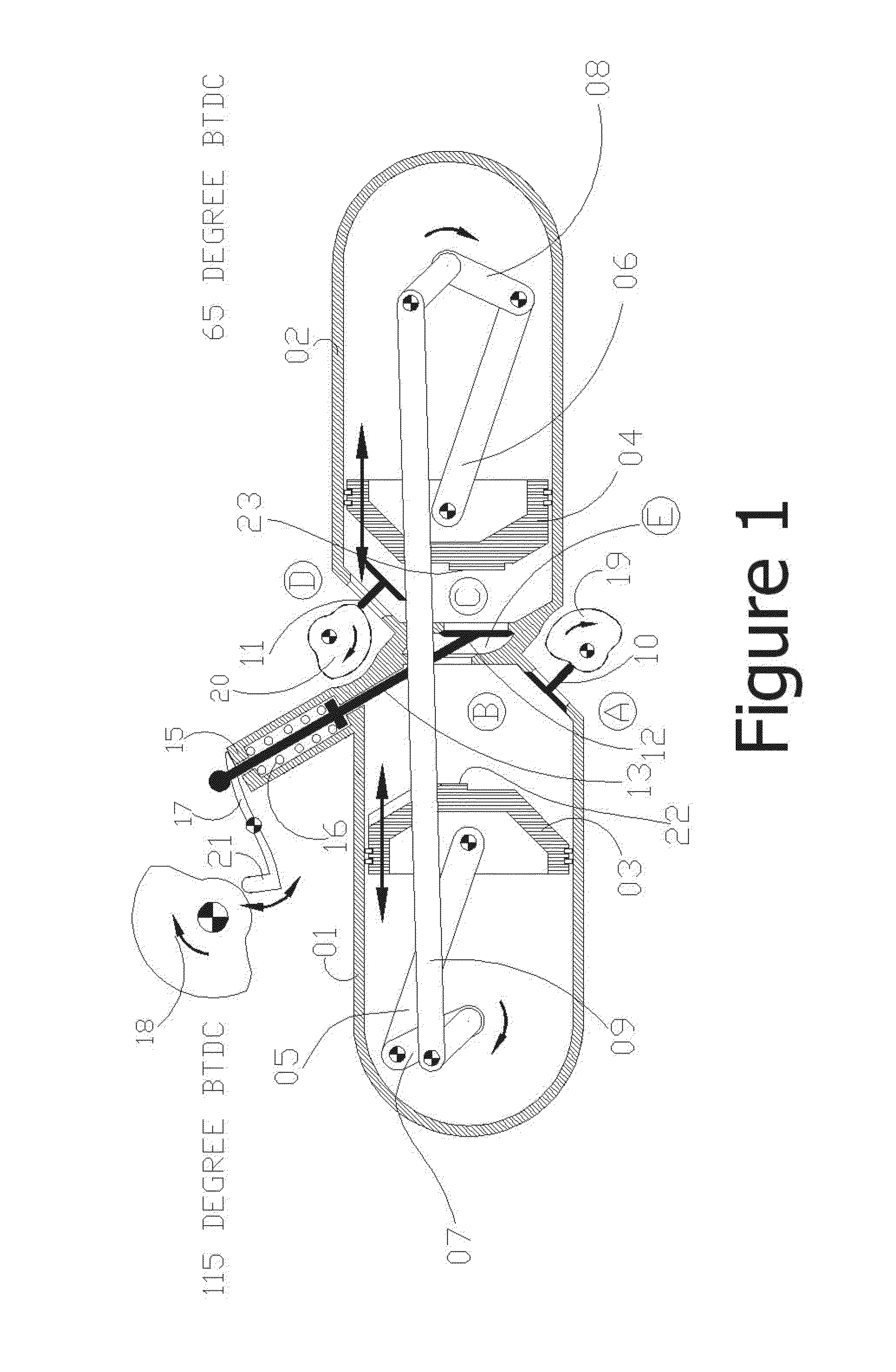
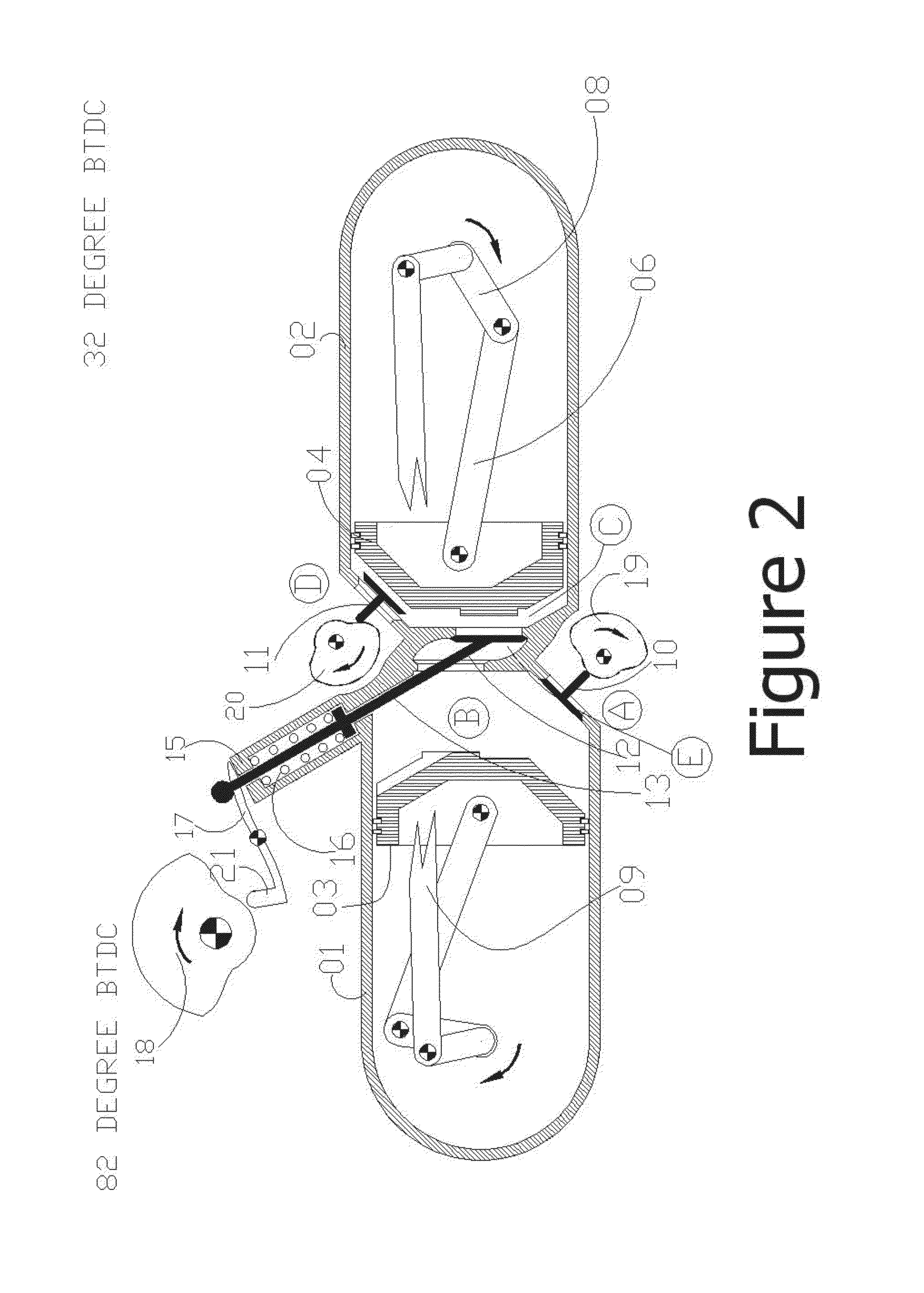
[0131]Referring to FIG. 1, in accordance with one embodiment of the present invention, a DPCE cylinder includes: a compression cylinder 01, a power cylinder 02, a compression piston 03, a power piston 04, two respective piston connecting rods 05 and 06, a compression crankshaft 07, a power crankshaft 08, a crankshaft connecting rod 09, an intake valve 10 that is operated by camshaft 19, an exhaust valve 11 that is operated by camshaft 20 and an crossover valve 12 that is operated by camshaft 18 via cam follower 21, rocker 17, and push / p...


PUM


Abstract

An internal combustion engine, including a combustion chamber with a first aperture; a compression chamber with a second aperture; and a crossover valve comprising an internal chamber, first and second valve seats, a valve head, and first and second valve faces on the valve head, wherein the first aperture allows fluid communication between the combustion chamber and the internal chamber, the second aperture allows fluid communication between the compression chamber and the internal chamber, the first valve face couples to the first valve seat to occlude the first aperture, and the second valve face couples to the second valve seat to occlude the second aperture.

Description

CROSS REFERENCE TO RELATED APPLICATIONS[0001]This application is a U.S. National Phase of International Application No. PCT / US2012 / 067477, filed Nov. 30, 2012 which claims the benefit of U.S. Provisional Application No. 61 / 565,286, filed Nov. 30, 2011, and U.S. Provisional. Application. No. 61 / 714,039, filed Oct. 15, 2012, the disclosures of which are herein incorporated by reference in their entireties.BACKGROUND OF THE INVENTION[0002]1. Field of the Invention[0003]The present invention relates generally to split-cycle internal combustion engines also known as split-cycle engines and, more specifically, to a Double Piston Cycle Engine (DPCE) that is more efficient than conventional combustion engines.[0004]2. Description of the Related Art[0005]Conventional internal combustion engines include one or more cylinders. Each cylinder includes a single piston that performs four strokes, commonly referred to as the intake, compression, combustion / power / expansion, and exhaust strokes. Toge...

Claims


Application Information

Patent Timeline
Patent Type & Authority Patents(United States)
IPC IPC(8): F02B33/22F02B33/18F02B19/18F02B19/02
CPCF02B33/22F02B33/18F02B19/02F02B19/18F02B2710/036F02B33/30
Inventor TOUR, HUGO BENJAMINTOUR, ODEDTOUR, GILAD
Owner TOUR ENGINE INC
Why Eureka
Try Eureka