Magnetic resonance device with diffusion gradient phase variation positionally corrected

a magnetic resonance and phase variation technology, applied in the field of diffusion spectroscopic imaging, can solve the problems of large motion artifacts, coherent phase variations due to object motion, and inability to generate motion artifacts, and achieve the effect of high-precision measuremen

Inactive Publication Date: 2015-08-04
HITACHI LTD
View PDF41 Cites 8 Cited by
  • Summary
  • Abstract
  • Description
  • Claims
  • Application Information

AI Technical Summary

Benefits of technology

[0025]According to the present invention, suppression of artifacts resulting from object motions of a measurement object and maintenance of SNR, spatial resolution, and spectral bandwidth can be simultaneously achieved, and highly precise measurement can be realized in the diffusion SI, in which, while chemical substances are separated, intensity of molecular diffusion thereof is imaged.

Problems solved by technology

However, since such positional changes due to object motion may be considered coherent phase variations, if DWI can be attained by one measurement, motion artifacts are not particularly generated.
In contrast, when phase encoding or signal accumulation is performed, coherent phase variations due to object motion generate motion artifacts.
Therefore, the motion artifacts tend to become larger.
Moreover, the influence of the signal attenuation at the time of signal accumulation cannot be disregarded, either.

Method used


Image

  • Magnetic resonance device with diffusion gradient phase variation positionally corrected
  • Magnetic resonance device with diffusion gradient phase variation positionally corrected
  • Magnetic resonance device with diffusion gradient phase variation positionally corrected

Examples


first embodiment

[0051]Hereafter, the present invention will be explained. In all of the drawings for explaining the embodiments of the present invention, elements having the same function are indicated with the same numerals or symbols, and repetition of the explanations thereof are omitted.

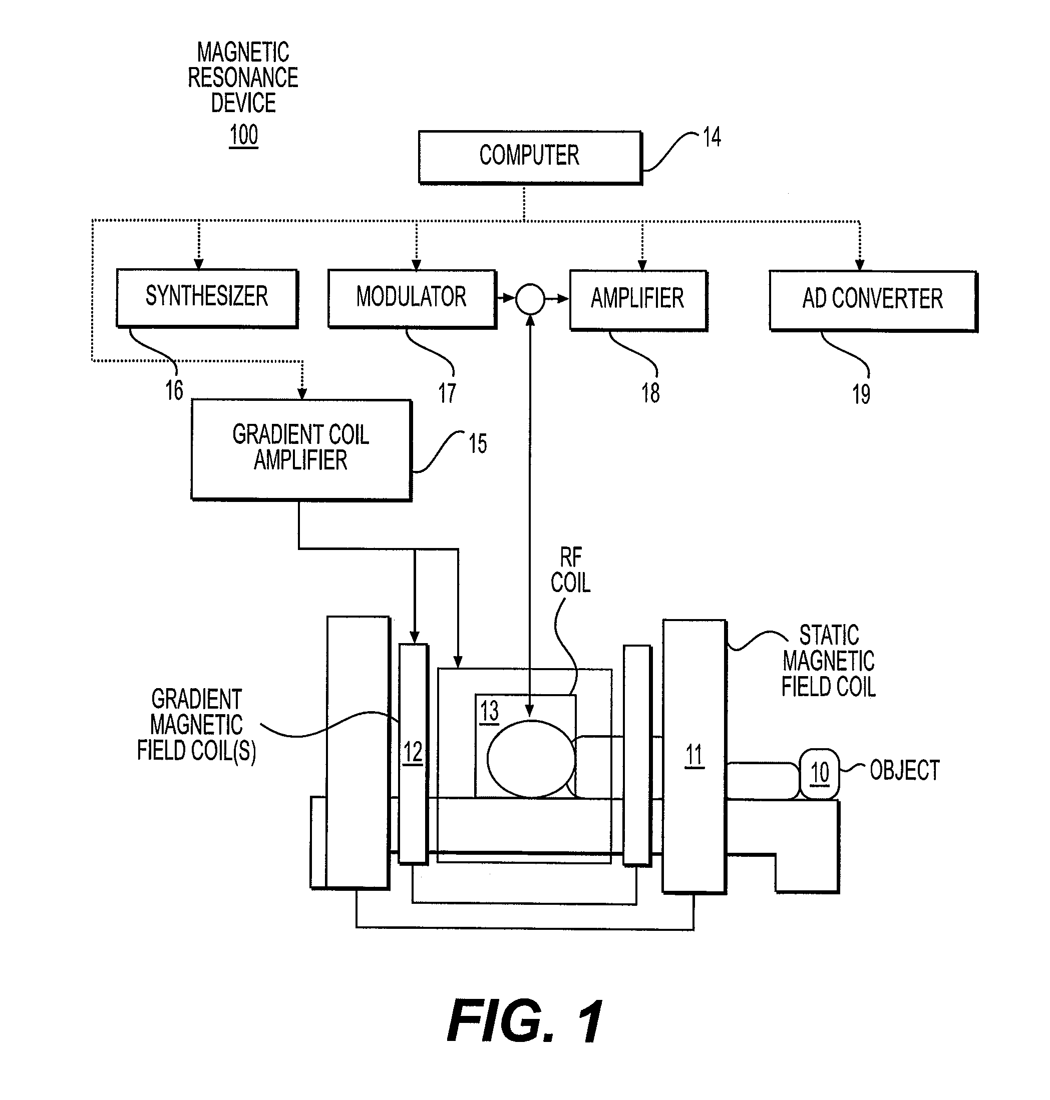
[0052]First, the device configuration of the magnetic resonance device of the present embodiment will be explained. FIG. 1 is a configurational diagram for explaining the outline of the magnetic resonance device 100 according to the present embodiment. The magnetic resonance device 100 is provided with a static magnetic field coil 11, a gradient magnetic field coil 12, a radio frequency coil 13, a computer 14, a gradient magnetic field amplifier 15, a synthesizer 16, a modulator 17, an amplifier 18, and an AD converter 19.

[0053]The synthesizer 16 generates a radio frequency wave, the modulator 17 modulates wave shape of the radio frequency wave generated by the synthesizer 16, amplifies it with electric power, a...

second embodiment

[0159]Moreover, as in the second embodiment, all the center frequencies mentioned above may be set to be the center frequency fc of spectral bandwidth, and positional shifts may be calculated from the difference of the resonance frequency fw of water and the center frequency fc of the spectral bandwidth, and corrected.

[0160]Furthermore, as in the second embodiment, when accurate resonance frequency fw of water cannot be obtained, two kinds of the navigator magnetic resonance signals 42 may be obtained by the method shown in FIG. 14A to estimate the resonance frequency fw of water.

>

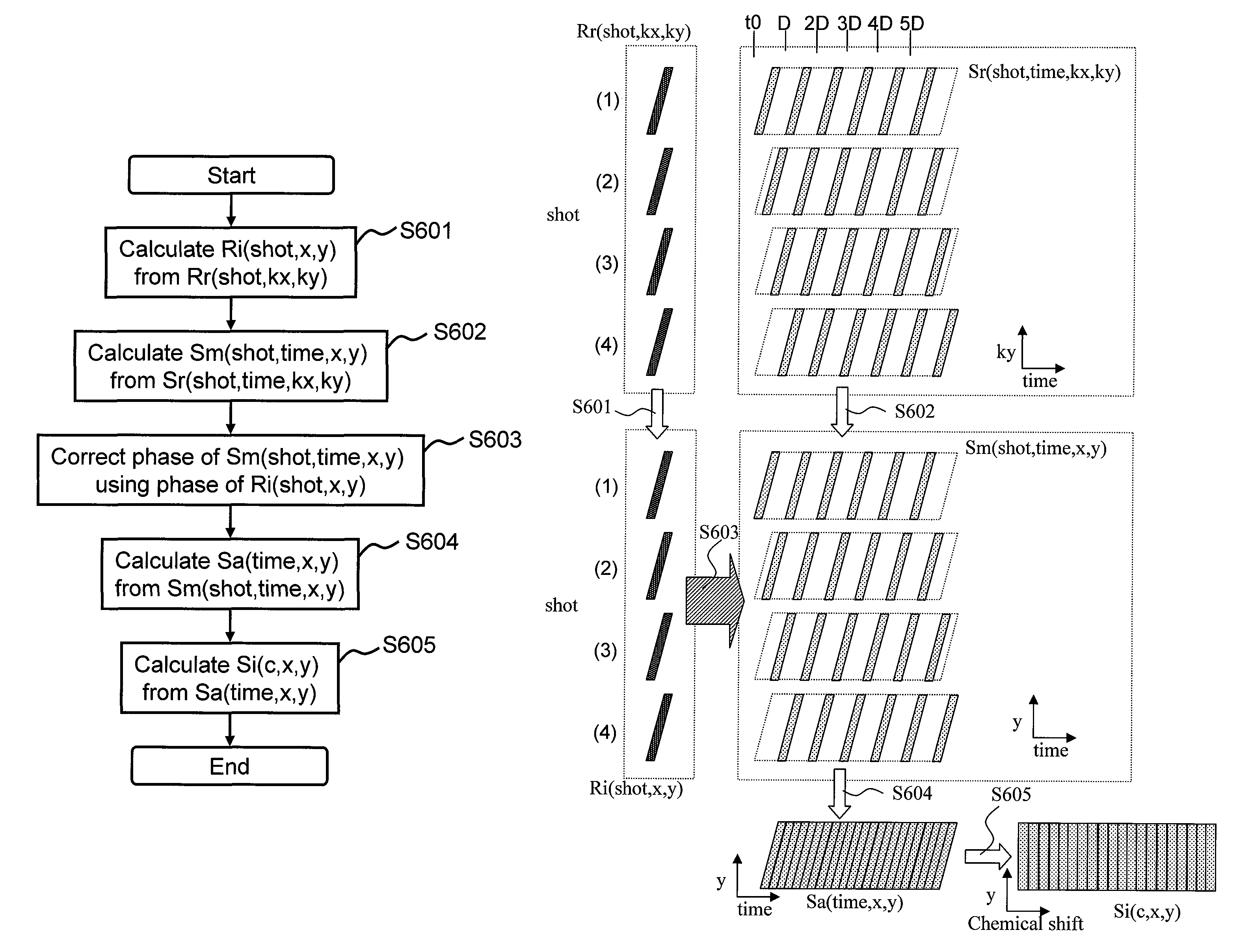
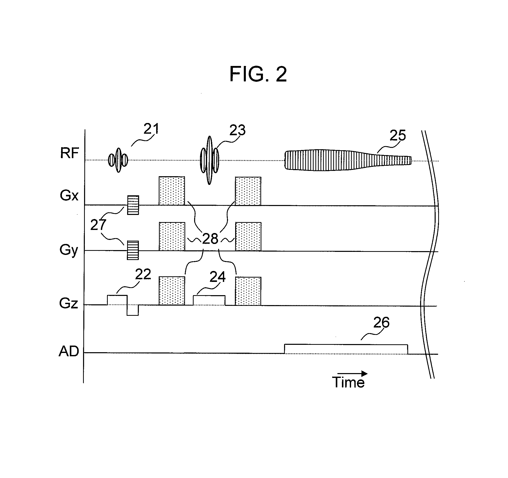
[0161]Hereafter, the fourth embodiment of the present invention will be explained. According to the present embodiment, navigation data are not obtained, but the phase used for correction is calculated from SI data. The magnetic resonance device of the present embodiment is basically the same as that of the first embodiment. The pulse sequence according to the present embodiment for controlling operations ...


PUM


Abstract

In the diffusion spectroscopic imaging, in which intensity of molecular diffusion is imaged with separating chemical substances, with suppressing artifacts resulting from object motion of an object, spatial resolution, spectral band and SNR are maintained, and measurement accuracy is enhanced. A measurement for acquiring diffusion SI data is repeated a plurality of times with changing acquisition timing, phase variation of each measurement result is corrected, and a diffusion SI image is reconstructed from the corrected measurement results. In addition, the phase variation is calculated for every point in the space from the diffusion SI data acquired by each measurement or navigation data obtained by each measurement. The phase correction is independently performed for every point in the space.

Description

TECHNICAL FIELD[0001]The present invention relates to a technique of diffusion spectroscopic imaging (SI), in which chemical substances are separated and spatial distribution of the molecular diffusion thereof is measured by using a magnetic resonance device.BACKGROUND ART[0002]Magnetic resonance devices are devices for obtaining (measuring) physicochemical information of an object by irradiating a radio frequency magnetic field of a specific frequency (RF pulse) on the object placed in a static magnetic field to induce a nuclear magnetic resonance phenomenon. Among the measurements using magnetic resonance devices, magnetic resonance imaging (MRI) is currently widely used, in which physical parameters varying depending on types of biological tissues such as proton density and difference of relaxation time are imaged. This technique also includes imaging in which signal intensities are modulated with physical parameters.[0003]The measurements using magnetic resonance devices also in...

Claims


Application Information

Patent Timeline
Patent Type & Authority Patents(United States)
IPC IPC(8): G01R33/485G01R33/563
CPCG01R33/485G01R33/56341
Inventor BITO, YOSHITAKAHIRATA, SATOSHIOCHI, HISAAKIHIRATA, KOJISHIRAI, TORUOTAKE, YOSUKE
Owner HITACHI LTD
Why Eureka
Try Eureka