Directional rotational atherectomy device with offset spinning abrasive element

a technology of rotating atherectomy and rotating abrasives, which is applied in the direction of hollow article cleaning, veterinary instruments, manufacturing tools, etc., can solve the problems of stent restenosis, block blood flow, and angina,

Inactive Publication Date: 2015-08-11
CARDIOVASCULAR SYST INC
View PDF53 Cites 24 Cited by
  • Summary
  • Abstract
  • Description
  • Claims
  • Application Information

AI Technical Summary

Benefits of technology

[0015]An object of the invention is to provide a rotational atherectomy device having a drive shaft with a pre-curved abrasive section for directional ablation.
[0021]Another object of the invention is to provide a rotational atherectomy device with a drive shaft capable of bi-directional rotation, wherein the abrasive element grinds in one rotational direction and cuts in the other rotational direction.
[0017]Another object of the invention is to provide a rotational atherectomy device comprising an abrasive element and / or cutting element at the midpoint and / or peak of the pre-curved section.
[0018]Another object of the invention is to provide a rotational atherectomy device comprising a pre-curved section with an abrasive zone and a cutting zone to allow achieving cutting and grinding / abrasion independently and within the same procedure.
[0019]Another object of the invention is to provide a rotational atherectomy device for directional ablation comprising a pre-curved drive shaft having at least one abrasive section thereon, wherein the operator controls which abrasive section, e.g., a grinding element or a cutting element, is exposed to the target tissue.
[0021]Another object of the invention is to provide a rotational atherectomy device with a drive shaft capable of bi-directional rotation, wherein the abrasive element grinds in one rotational direction and cuts in the other rotational direction.
[0021]Another object of the invention is to provide a rotational atherectomy device with a drive shaft capable of bi-directional rotation, wherein the abrasive element grinds in one rotational direction and cuts in the other rotational direction.
[0022]Another object of the invention is to provide a rotational atherectomy device with a pre-curved region of the drive shaft and comprising an eccentric enlarged section of the drive shaft within the pre-curved region to induce orbital spinning motion by moving the center of mass radially off of one of several axes of rotation of the directional element of the drive shaft for directional ablation.
[0022]Another object of the invention is to provide a rotational atherectomy device with a pre-curved region of the drive shaft and comprising an eccentric enlarged section of the drive shaft within the pre-curved region to induce orbital spinning motion by moving the center of mass radially off of one of several axes of rotation of the directional element of the drive shaft for directional ablation.
[0022]Another object of the invention is to provide a rotational atherectomy device with a pre-curved region of the drive shaft and comprising an eccentric enlarged section of the drive shaft within the pre-curved region to induce orbital spinning motion by moving the center of mass radially off of one of several axes of rotation of the directional element of the drive shaft for directional ablation.
[0028]Another object of the invention is to provide a rotational atherectomy device with a pre-curved region of the drive shaft and comprising an abrasive annular ring attached to the drive shaft within the pre-curved region for directional ablation.
[0028]Another object of the invention is to provide a rotational atherectomy device with a pre-curved region of the drive shaft and comprising an abrasive annular ring attached to the drive shaft within the pre-curved region for directional ablation.
[0022]Another object of the invention is to provide a rotational atherectomy device with a pre-curved region of the drive shaft and comprising an eccentric enlarged section of the drive shaft within the pre-curved region to induce orbital spinning motion by moving the center of mass radially off of one of several axes of rotation of the directional element of the drive shaft for directional ablation.
[0028]Another object of the invention is to provide a rotational atherectomy device with a pre-curved region of the drive shaft and comprising an abrasive annular ring attached to the drive shaft within the pre-curved region for directional ablation.
[0029]Another object of the invention is to provide a rotational atherectomy device comprising user control of the magnitude of radial expansion of the pre-curved section.
[0030]Another object of the invention is to provide a rotational atherectomy device for directional ablation comprising a pre-curved drive shaft with abrasive section thereon, wherein the curvilinear profile characteristics, e.g., height and length, of the pre-curved section are controlled by the operator.
[0031]Another object of the invention is to provide a system and methods to achieve, inter alia, the above objectives.

Problems solved by technology

If left untreated, such stenoses can cause angina, hypertension, myocardial infarction, strokes and the like.
Studies have shown, however, that a significant percentage of patients who have undergone balloon angioplasty and had a stent placed in an artery experience stent restenosis—i.e., blockage of the stent which most frequently develops over a period of time as a result of excessive growth of scar tissue within the stent.
As the burr is removing stenotic tissue, however, it blocks blood flow.
This construction is limited, however because, as Clement explains at Col. 3, lines 53-55, that the asymmetrical burr is rotated at “lower speeds than are used with high speed ablation devices, to compensate for heat or imbalance.” That is, given both the size and mass of the solid burr, it is infeasible to rotate the burr at the high speeds used during atherectomy procedures, i.e., rotational speeds within the range of about 20,000-200,000 rpm.
Essentially, the center of mass offset from the rotational axis of the drive shaft would result in development of significant and undesirable centrifugal force, exerting too much pressure on the wall of the artery and creating too much heat and excessively large particles.
This flexion allows for a larger diameter opening during high speed operation, but may also provide less control than desired over the diameter of the artery actually abraded.
Further, the pre-curved guide wire approach may find difficulty in traversing the often tortuous vasculature enroute to the stenosis of interest.
Moreover, the pre-curved guide wire devices are not designed for focused directional ablation.

Method used


Image

  • Directional rotational atherectomy device with offset spinning abrasive element
  • Directional rotational atherectomy device with offset spinning abrasive element
  • Directional rotational atherectomy device with offset spinning abrasive element

Examples


Embodiment Construction

[0043]While the invention is amenable to various modifications and alternative forms, specifics thereof are shown by way of example in the drawings and described in detail herein. It should be understood, however, that the intention is not to limit the invention to the particular embodiments described. On the contrary, the intention is to cover all modifications, equivalents, and alternatives falling within the spirit and scope of the invention.

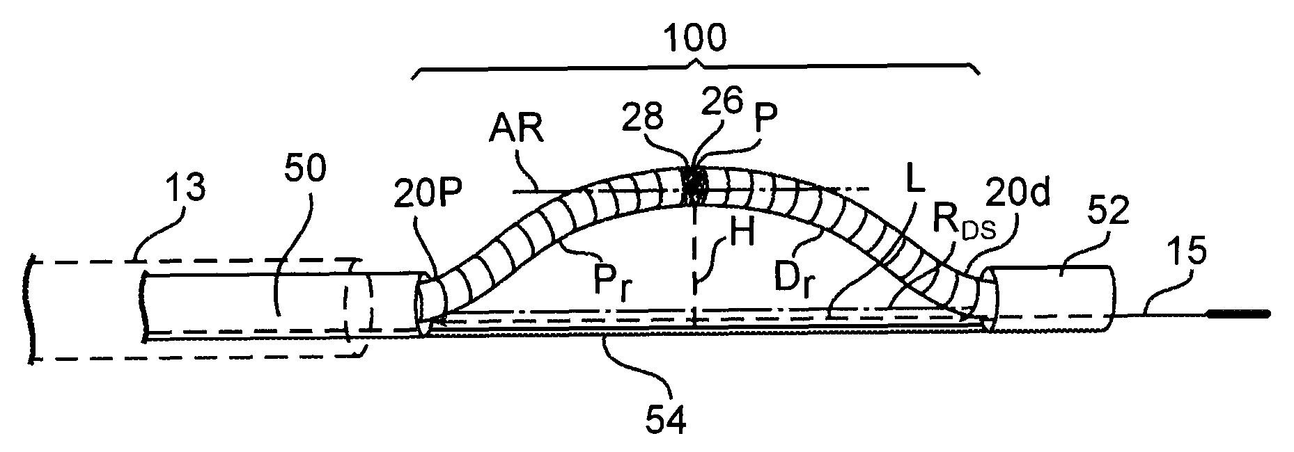
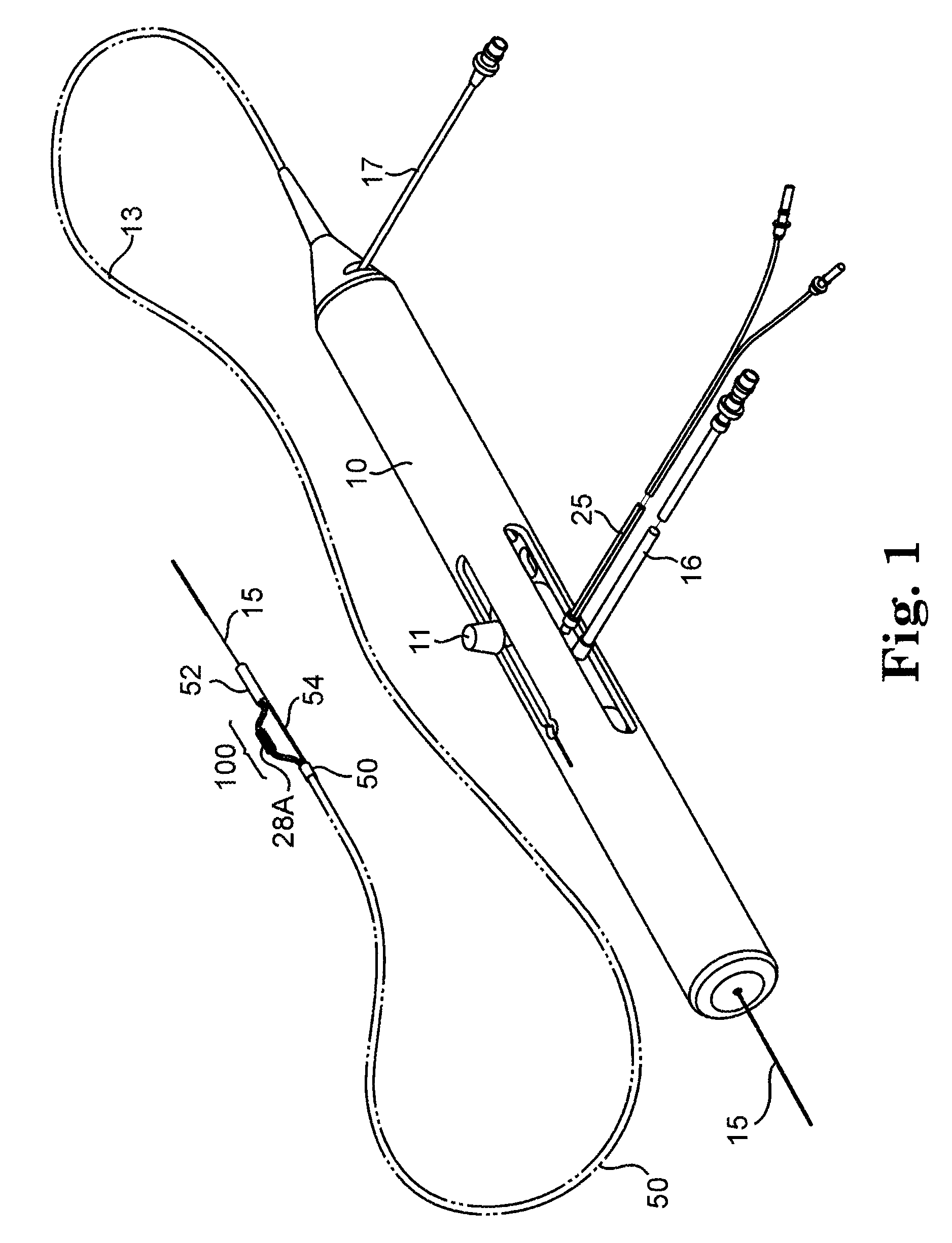
[0044]FIG. 1 illustrates one embodiment of a rotational atherectomy system and device of the present invention. The system includes a handle portion 10, an elongated, flexible drive shaft 20 having a pre-curved section 100 which further comprises an abrasive section or element 28, illustrated without limitation as a concentric atherectomy crown 28A, which is attached to drive shaft 20 within pre-curved section 100. The drive shaft 20 may be, as is well known in the art, constructed from helically coiled wire(s). Drive shaft also comprises a p...


PUM

PropertyMeasurementUnit
diameteraaaaaaaaaa
outer diameteraaaaaaaaaa
flexibleaaaaaaaaaa

Abstract

The invention provides a rotational atherectomy system, device and method comprising a flexible, elongated, rotatable drive shaft with a pre-curved abrasive section disposed within a catheter that deforms the abrasive section to a substantially straight profile and, when the abrasive section is moved distally out of the catheter, the abrasive section resumes its pre-curved profile. Directional ablation is achieved by rotation of the drive shaft along its pre-curved axis as the abrasive section is urged against a portion of the lumen wall.

Description

CROSS-REFERENCE TO RELATED APPLICATIONS[0001]The present application claims priority to provisional application No. 61 / 058,958, filed on Jun. 5, 2008 under the title, “SPINNING OFFSET CUTTER LARGE VESSEL ATHERECTOMY DEVICE”, the contents of which are incorporated by reference herein.BACKGROUND OF THE INVENTION[0002]1. Field of the Invention[0003]The invention relates to devices and methods for removing tissue from body passageways, such as removal of atherosclerotic plaque from arteries, utilizing a rotational atherectomy device.[0004]2. Description of the Related Art[0005]A variety of techniques and instruments have been developed for use in the removal or repair of tissue in arteries and similar body passageways. A frequent objective of such techniques and instruments is the removal of atherosclerotic plaques in a patient's arteries. Atherosclerosis is characterized by the buildup of fatty deposits (atheromas) in the intimal layer (under the endothelium) of a patient's blood vesse...

Claims


Application Information

Patent Timeline
Patent Type & Authority Patents(United States)
IPC IPC(8): A61B17/22A61B17/3207A61B17/32
CPCA61B17/320758Y10T29/49863A61B2017/320004A61B2017/320766
Inventor PLOWE, CHARLES A.DARLEY, JESSE C.FRANCHINO, DAVID C.CAMBRONNE, MATTHEW D.RIVERS, JODYPIIPPO, CASSANDRA A.KOHLER, ROBERT E.
Owner CARDIOVASCULAR SYST INC
Why Eureka
Try Eureka