
Drying tray and method of use

a technology of drying tray and trays, which is applied in the field of trays, can solve the problems of loss of even and consistent dehydration quality, unsatisfactory sealing of the outer surface of the product, and lack of uniformity of the environment to which the product is exposed,

Inactive Publication Date: 2015-08-11
HARTWELL WARREN R +1
View PDF9 Cites 2 Cited by
  • Summary
  • Abstract
  • Description
  • Claims
  • Application Information

AI Technical Summary

Benefits of technology

The polymer-based trays ensure consistent and efficient dehydration, prevent contamination, and reduce product damage by maintaining even air circulation and heat absorption, while being easy to clean and stack, thus improving the reliability and performance of the drying process.

Problems solved by technology

For example, case hardening can undesirably seal the outer surface of a product and prevent moisture from escaping from the product during drying.
While some products react well to this procedure, most do not.
The loss of the even and consistent dehydration quality motivates most operators to investigate other drying protocols.
The problem with batch drying is in the lack of uniformity of the environment the product is exposed to.
Existing drying trays have been traditionally made from laminated, composite or hardwood with the following problems: wooden trays can absorb water, juice, flavors, and odors; wooden trays can harbor bacteria, microbes, nematodes, black algae, fungus, and other potential contamination; wooden tray's splinters and chips can contaminate the food product; wooden trays are hard to clean and products can be damaged and deformed when being scraped from the tray surface; wooden trays need to be screwed or nailed together, such fixtures can easily work free and contaminate products or jam handling systems; wooden trays can absorb heat quickly and burn or discolor the surface of the fruit that lays against the wood.
Stainless steel trays are somewhat uncommon due to high cost, hard to release surface, high heat transfer burning fruits, and less than optimal footprint (smaller sized due to handling weight).

Method used


Image

  • Drying tray and method of use
  • Drying tray and method of use
  • Drying tray and method of use

Examples


Embodiment Construction

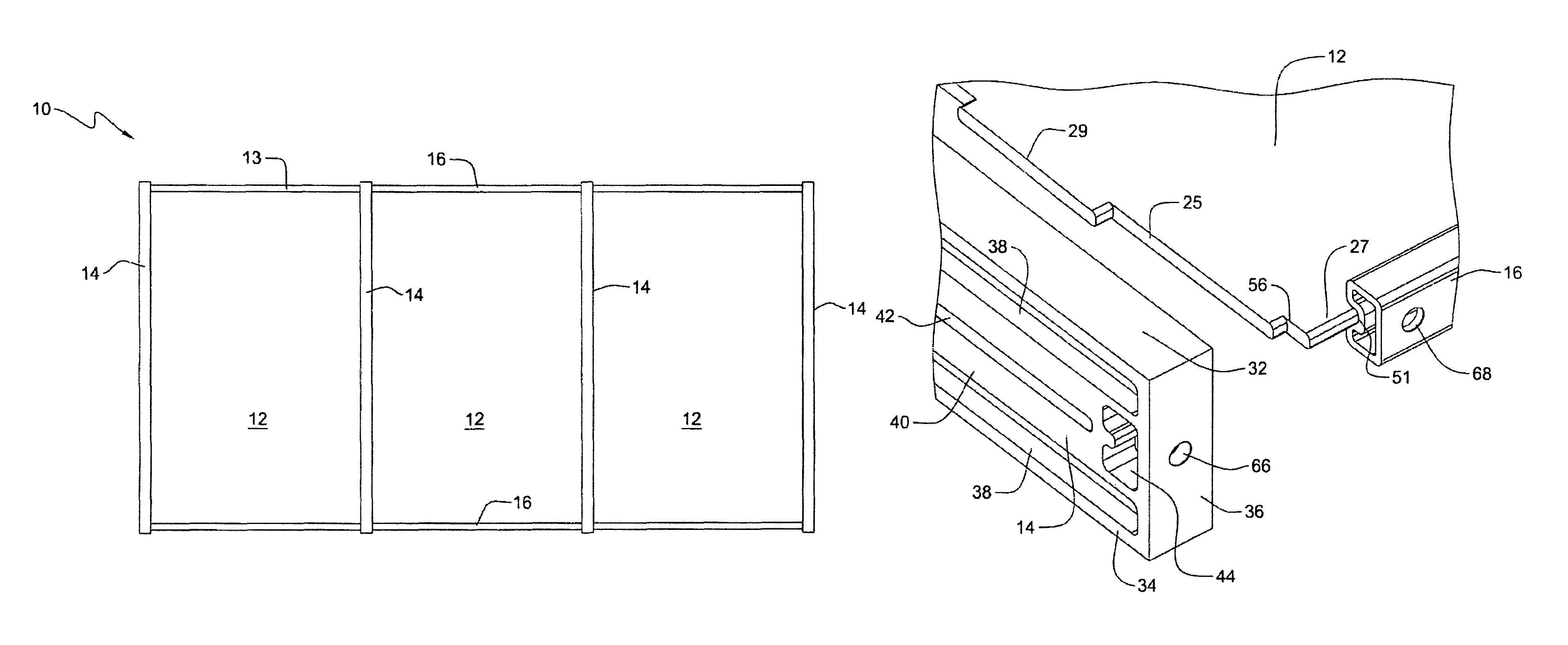
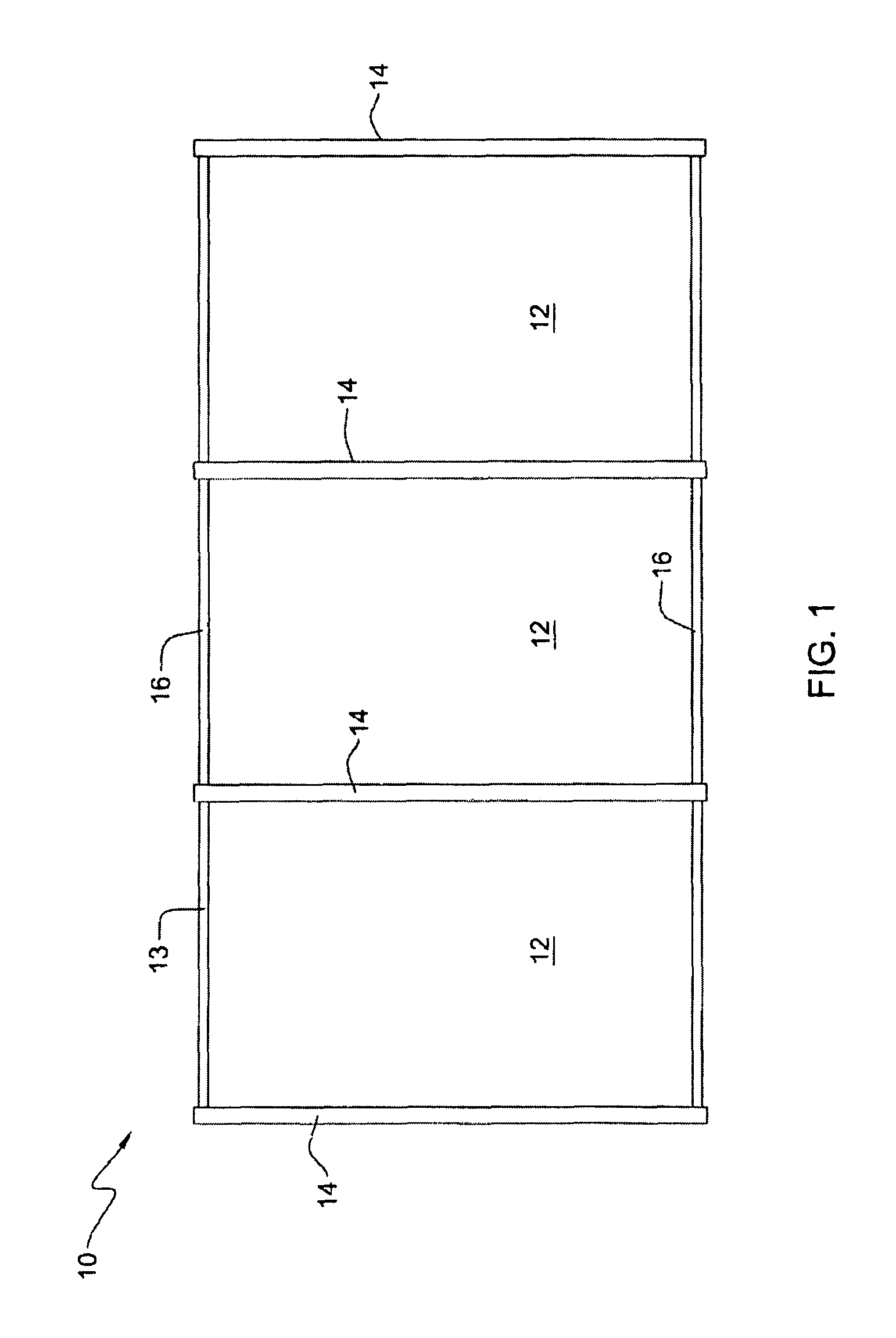
[0041]FIG. 1 is a plan view of a produce drying tray 10 according to one aspect of the invention. Though tray 10 may be used for a broad range of applications, including for transport, storage, or other handling of miscellaneous articles, according to one aspect of the invention, tray 10 may be used to retain produce, for example, fruits and vegetables, while the produce is dried, for example, in the production of dried fruits, such as prunes, or dried vegetable, such as, sun-dried tomatoes.

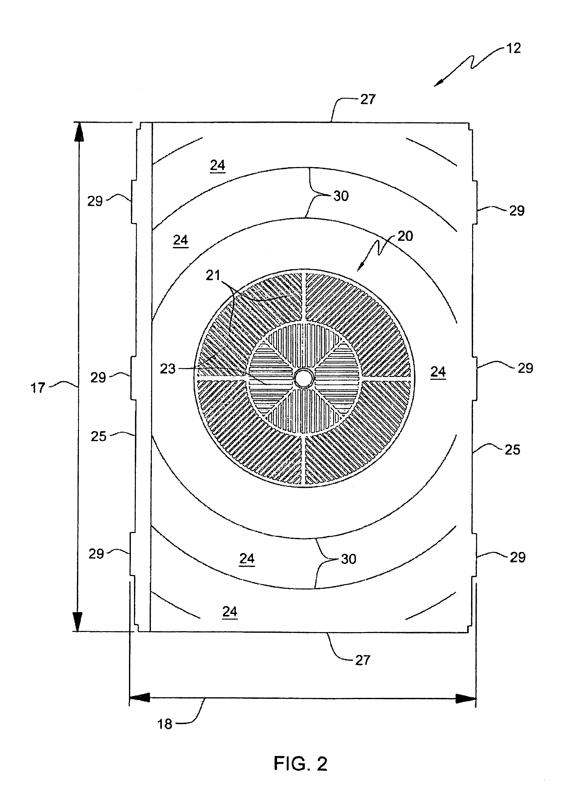
[0042]According to aspects of the present invention, tray 10 comprises one or more panel sections, deck panels, or panels 12 and a support frame 13 adapted to support the panels 12. Frame 13 comprises a plurality of lateral support members 14 and a plurality of longitudinal support members 16, for example, elongated support members. Though in one aspect of the invention, frame 13 may be provided as an assembly of inter-engaging members 14 and 16, in one aspect, frame 13 may be provided as a subst...


PUM


Abstract

A tray, for example, a drying tray, a method for drying, and a structural member engagement system are provided. The drying tray includes at least one perforated panel; and a frame adapted to support the perforated panel. The frame may include a plurality of interconnecting plastic support members adapted to receive the perforated panel. The tray may be used to dry fruits, vegetables, fish, and meat. A method of using the tray and a structural member engagement system are also disclosed The member engagement system includes a first elongated member, a second elongated member, and a plug and pin adapted to engage the first member with the second member.

Description

CROSS-REFERENCE TO RELATED APPLICATION[0001]This application claims priority from pending U.S. Provisional Patent Application 60 / 988,242, filed on Nov. 15, 2007, the disclosure of which is included by reference herein in its entirety.BACKGROUND OF THE INVENTION[0002]1. Field of the Invention[0003]The present invention generally relates to trays, a tray construction, and methods of using trays. More particularly, the present invention relates to a drying or dehydration trays and their methods of use, for example, in drying produce such as fruits or vegetables.[0004]2. Description of Related Art[0005]Between 1910 and 1920, L. N. Miller invented a box-like dryer for drying produce. The dryer was heated artificially by oil and included a large fan capable of high air velocity, humidity shutters, and bleeder vents. This was the predominant design for dryers through the 1940s and spawned many variations.[0006]In the 1960s, scientists at the University of California at Davis developed the ...

Claims


Application Information

Patent Timeline
Patent Type & Authority Patents(United States)
IPC IPC(8): F26B25/18
CPCF26B25/18
Inventor HARTWELL, WARREN R.BARTLEY, PAUL E.
Owner HARTWELL WARREN R
Learn More