Alignment method for optical axes of composite waveplate

a composite waveplate and alignment method technology, applied in the field of composite waveplate alignment, can solve the problems of inability to meet inability to guarantee the alignment accuracy of the single crystal plate to achieve the functions of the composite waveplate, and difficulty in meeting the requirements of high measurement accuracy. achieve the effect of eliminating fluctuation in spectral parameters and accurate alignment methods

Active Publication Date: 2015-08-11
WUHAN EOPTICS TECH CO LTD
View PDF1 Cites 0 Cited by
  • Summary
  • Abstract
  • Description
  • Claims
  • Application Information

AI Technical Summary

Benefits of technology

[0010]In view of the above-mentioned problems, it is one objective of the invention to provide an accurate alignment method for the optical axes of a composite waveplate by detecting and eliminating fluctuation in spectral parameters of the composite waveplate.
[0024]Generally, people only care about a retardance of a waveplate, and normally a detection device can only determine the value of the retardance. Because the fluctuation amplitude of a retardance curve is insensitive to an alignment error of the composite waveplate and because the accuracy of the detection device is limited, alignment accuracy of the composite waveplate in methods of using the retardance curve cannot be ensured. The method of the invention can simultaneously detect fluctuation in spectral curves of an equivalent retardance spectrum, an equivalent axis azimuth spectrum, and an equivalent rotary angle spectrum of the composite waveplate. Since the fluctuation in the spectral curves of the equivalent axis azimuth spectrum and the equivalent rotary angle spectrum is highly sensitive to the alignment error of the composite waveplate, the method of the invention achieves accurate alignment of the composite waveplate even when the detection accuracy of the detection device for the spectral parameters is limited.
[0028]Compared to a conventional alignment method for optical axes of a composite waveplate, the alignment method of the invention detects and controls the fluctuation amplitudes of the three equivalent spectral parameters, including the equivalent retardance spectrum, the equivalent axis azimuth spectrum, and the equivalent rotary angle spectrum of the composite waveplate, via an optical detection and analyzing system according to the equivalent model of the composite waveplate, whereby achieving high accuracy alignment of the optical axes of the composite waveplate. The invention features simple operation, controllable alignment accuracy, and wide application prospect in optical instrument design and optical measurement.

Problems solved by technology

It is impossible for a single crystal plate to achieve the functions of the composite waveplate in improving accuracy and eliminating the chromatic aberration.
Although operation of the manual alignment method is comparatively simple, alignment accuracy thereof cannot be guaranteed, which makes it difficult to meet requirement for high measurement accuracy.
However, the light extinction method has one problem because light extinction often occurs at one specific wavelength, and it is difficult to determine whether the optical axes of the waveplate is accurately aligned according to light extinction of the single specific wavelength.
To solve this problem, laser light sources with different wavelengths need to be used, and correspondingly optical paths need to be adjusted in accordance with the different wavelengths, which results in complex operation and low alignment accuracy.
Although the accuracy of this alignment method is higher than that of the conventional manual alignment method, final alignment accuracy is largely dependent on the experience of the operator due to the complexity of this alignment process.
However, since fluctuation in the spectral curve of retardance of the composite waveplate is not sensitive to an alignment error between composite waveplates, alignment accuracy thereof cannot be ensured when the accuracy of a device for detecting retardance is not high enough.

Method used


Image

  • Alignment method for optical axes of composite waveplate
  • Alignment method for optical axes of composite waveplate
  • Alignment method for optical axes of composite waveplate

Examples


Embodiment Construction

[0037]For clear understanding of the objectives, features, and advantages of the invention, detailed description of the invention will be given below in conjunction with accompanying drawings and specific embodiments. It should be noted that the embodiments are only meant to explain the invention, and not to limit the scope of the invention.

[0038]To clearly illustrate an alignment method for optical axes of a composite waveplate of the invention, a dual rotating-compensator Mueller matrix ellipsometer is illustratively and advantageously used for detection of spectral parameters of the waveplate.

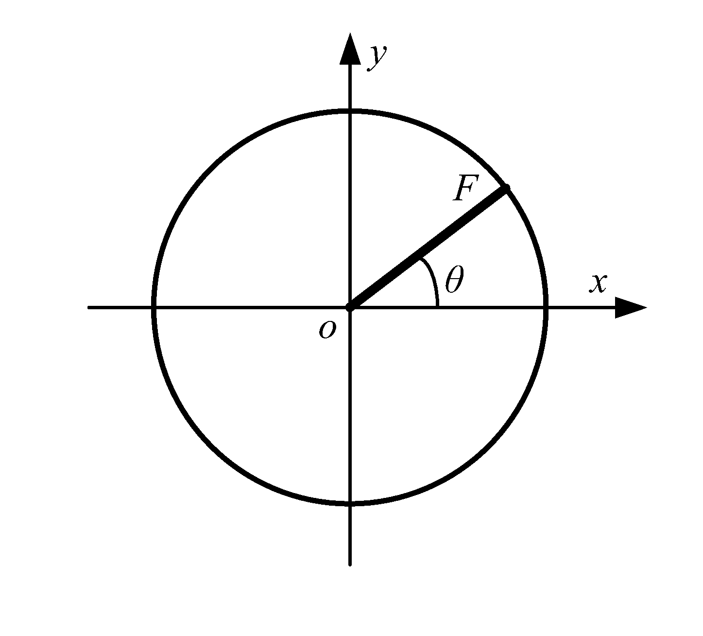
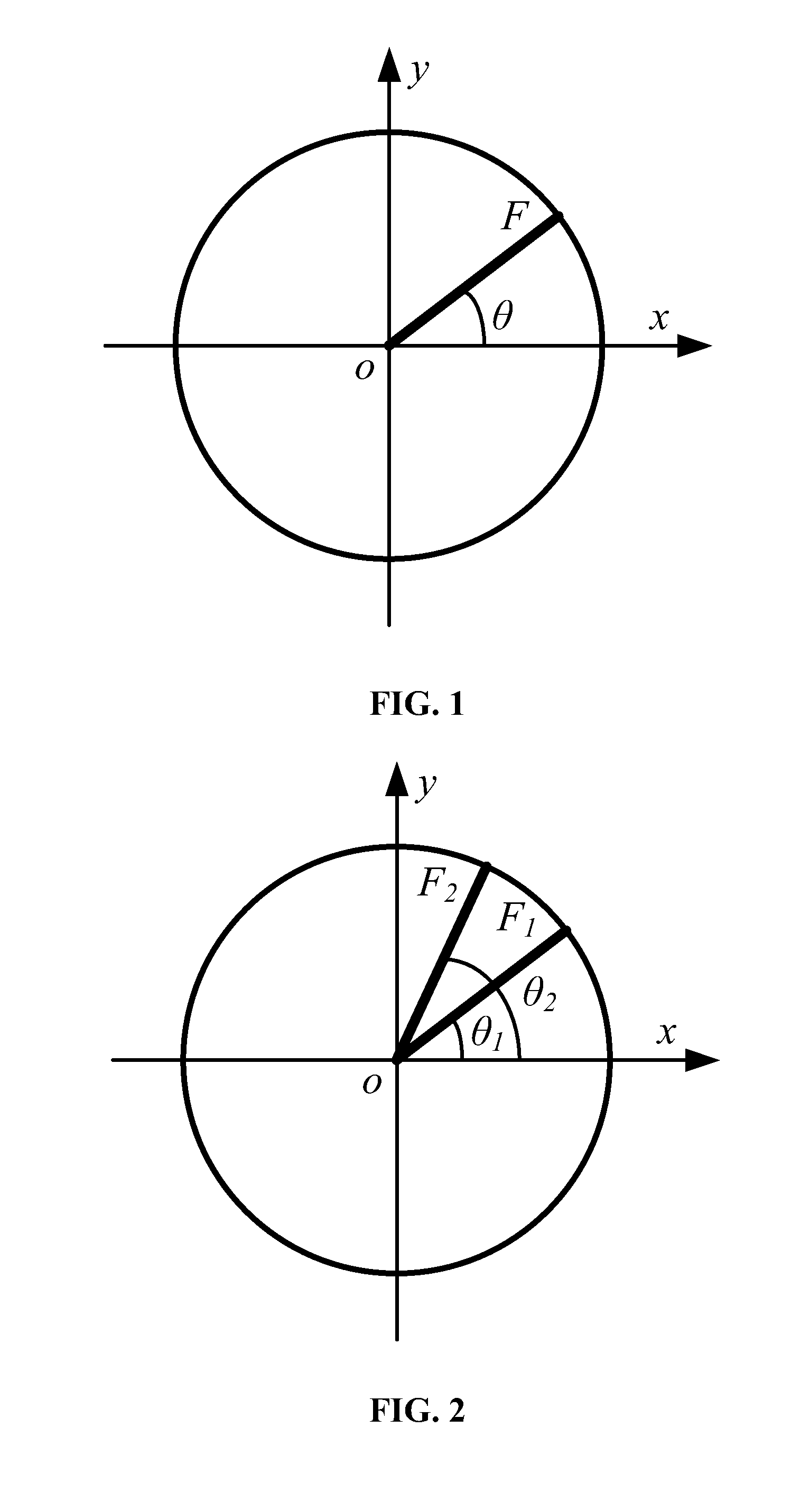
[0039]As shown in FIG. 1, in an x-o-y coordinate, an angle formed by a fast axis (F axis) of the waveplate and the x axis is θ; a retardance of the waveplate is δ; and a transmission characteristic of the waveplate is expressed as the following equation (1):

[0040]M⁡(δ,θ)=[cos⁢⁢θ-sin⁢⁢θsin⁢⁢θcos⁢⁢θ]⁡[ⅇⅈ⁢⁢δ / 200ⅇ-ⅈ⁢⁢δ / 2]⁡[cos⁢⁢θsin⁢⁢θ-sin⁢⁢θcos⁢⁢θ](1)

where i represents the imaginary unit, and δ...


PUM


Abstract

An alignment method for optical axes of a composite waveplate includes rotating a rotatable waveplate, which rotates about a central axis with respect to a fixed waveplate, and adjusting the rotation angle thereof until the differences between the spectral parameters of the composite waveplate and ideal spectral parameters are smaller than preset values.

Description

CROSS-REFERENCES TO RELATED APPLICATIONS[0001]Pursuant to 35 U.S.C. §119 and the Paris Convention Treaty, this application claims the benefit of Chinese Patent Application No. 201310320167.1 filed Jul. 26, 2013, the contents of which are incorporated herein by reference. Inquiries from the public to applicants or assignees concerning this document or the related applications should be directed to: Matthias Scholl P.C., Attn.: Dr. Matthias Scholl Esq., 245 First Street, 18th Floor, Cambridge, Mass. 02142.BACKGROUND OF THE INVENTION[0002]1. Field of the Invention[0003]The invention generally relates to the field of composite waveplates, and more particularly to an alignment method for optical axes of a composite waveplate. The method of the invention is suitable for accurate alignment and calibration of optical axes of a composite waveplate consisting of two or more single crystal plates.[0004]2. Description of the Related Art[0005]A waveplate (also known as optical phase retardation ...

Claims


Application Information

Patent Timeline
Patent Type & Authority Patents(United States)
IPC IPC(8): G01J3/28G01B11/27G02B27/62G02B5/30G02B7/00
CPCG02B27/62G02B5/3083G01B11/272
Inventor LIU, SHIYUANGU, HONGGANGCHEN, XIUGUOZHANG, CHUANWEILI, WEIQIDU, WEICHAO
Owner WUHAN EOPTICS TECH CO LTD
Why Eureka
Try Eureka