Portable programmable ladar test target

a ladar and target technology, applied in the field of laser detection and ranging or light detection and ranging systems, can solve the problems of lack of ladar/lidar system testing techniques that can be implemented in the field of portable ladar/lidar testing targets, small laboratory or portable indoor ladar/lidar testing currently limited to one dimensional targets,

Active Publication Date: 2015-08-18
RAYTHEON CO
View PDF8 Cites 30 Cited by
  • Summary
  • Abstract
  • Description
  • Claims
  • Application Information

AI Technical Summary

Benefits of technology

[0006]Certain embodiments may provide various technical advantages depending on the implementation. For example, certain embodiments provide a return signal transmission including outputs from multiple fiber optical delay lines of different lengths corresponding to different ranges, which together correlate to a three dimensional object. Certain embodiments simulate an unsmooth or non-flat surfaced target to the LADAR or LiDAR. Certain embodiments utilize an electronically programmable delay adding to the fiber optic target spool(s) delay which determines the total delay or range. Certain embodiments utilize one or two rotation...

Problems solved by technology

However, small laboratory or portable indoor LADAR/LiDAR testing is currently limited to one dimensional targets at one range similar to laser rangefinder testing.
Otherwise, compact indoor LADAR/LiDAR testing is limited to indoor testing of LADAR/LiDAR components via methods such as indoor...

Method used


Image

  • Portable programmable ladar test target
  • Portable programmable ladar test target
  • Portable programmable ladar test target

Examples


Embodiment Construction

[0015]It should be understood at the outset that, although example embodiments are illustrated below, the present invention may be implemented using any number of techniques, whether currently known or not. The present invention should in no way be limited to the example implementations, drawings, and techniques illustrated below. Additionally, the drawings are not necessarily drawn to scale.

[0016]The following document is hereby incorporated into the present disclosure as if fully set forth herein: (i) U.S. Pat. No. 8,399,872 (hereinafter “REF1”).

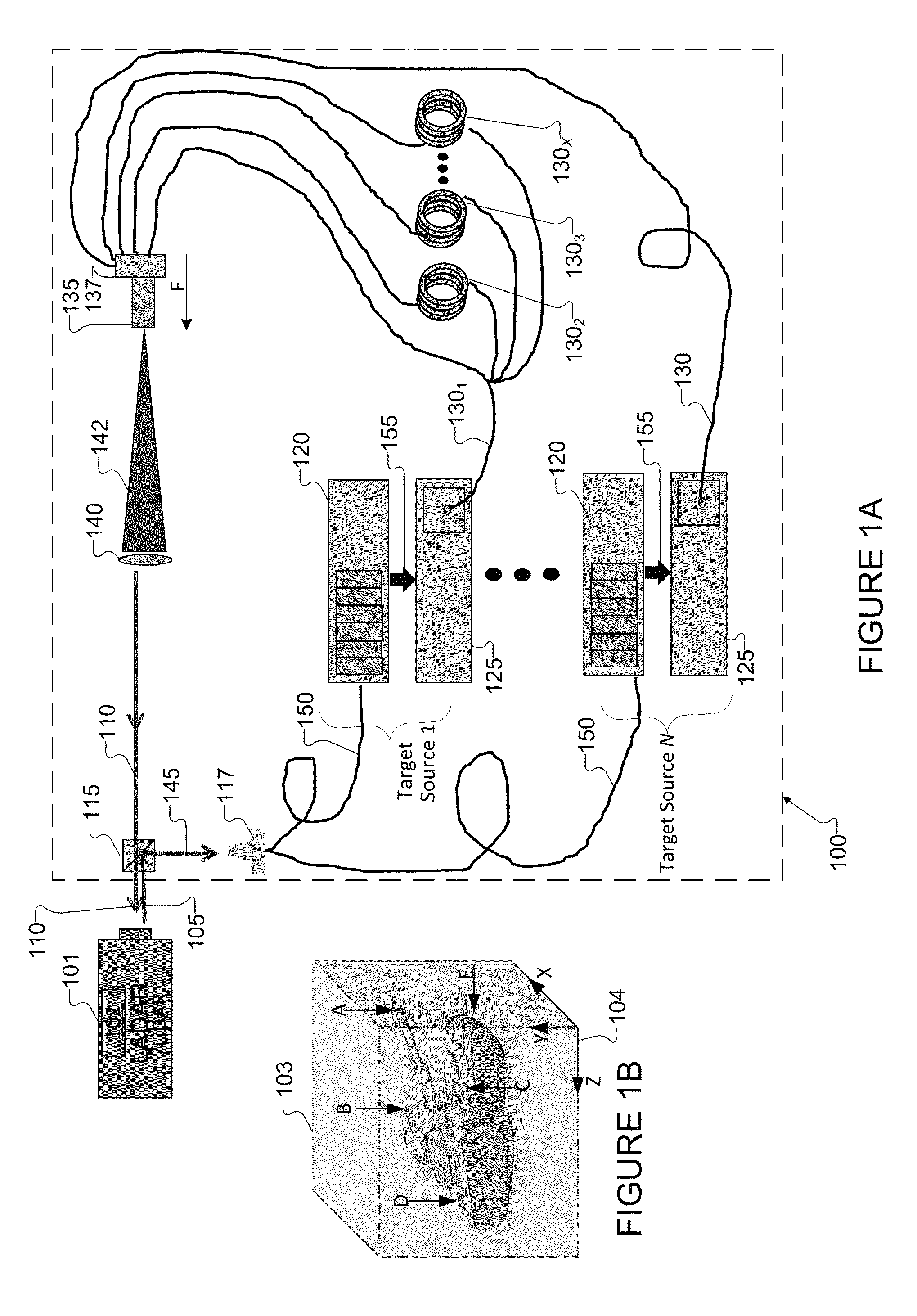
[0017]There are a few methods and test equipment to test a rangefinder using a simulated targeted object. One solution is a simulated range technique using a simulated optical range target (SORT). The simulated optical range target (SORT) includes a lens, a spool of fiber optical delay line with a mirror at the end of the line. Laser energy is transmitted into the lens. The lens focuses the laser energy into a first end of the fiber optica...


PUM


Abstract

A method of testing a Laser Detection and Ranging (LADAR) or LIght Detection And Ranging (LiDAR) system includes receiving an input signal from the LADAR/LiDAR and triggering light/laser sources to output pulses. The method includes transmitting the light/laser pulses into a first end of two or more fiber optical delay lines. The method includes transmitting the pulses throughout a length of two or more fiber optical delay lines. The method includes after a delay time corresponding to the length of the fiber optical delay lines, transmitting the pulses out through a second end of the fiber optical delay lines arranged within a target plane. The pulses output yield a return signals transmission from the target plane to the LADAR/LiDAR. The return signal transmission is delayed by times for the light/laser pulses to traverse the length of the fiber optical delay lines.

Description

TECHNICAL FIELD[0001]The present disclosure is directed in general to testing equipment for laser and light ranging systems and more specifically to systems and methods testing Laser Detection and Ranging (LADAR) or Light Detection And Ranging (LIDAR) systems.BACKGROUND OF THE DISCLOSURE[0002]Ranging is a process of determining the distance from one position to another position. The various types of ranging systems (namely, RAdio Detection And Ranging (RADAR), LIght Detection And Ranging (LiDAR), and LAser Detection And Ranging (LADAR)) transmit and receive electromagnetic energy. The ranging system (also referred to as “rangefinder” or “ranging equipment”) includes a signal generator and transmitter that transmit an electromagnetic signal to a targeted object. The electromagnetic signal interacts with the targeted object, which reflects a portion of the electromagnetic signal. The ranging system includes a receiver that receives the reflected electromagnetic signal and transforms t...

Claims


Application Information

Patent Timeline
IPC IPC(8): G01S7/486G01S7/497G01S17/08G01C3/08G01S17/10G01S7/4865G01S17/26
CPCG01S7/497G01S17/08G01S17/10G01S7/4865G01S17/102G01S17/26
Inventor BATES, KENN S.PEIRCE, ROBERT L.
Owner RAYTHEON CO
Why Eureka
Try Eureka