Vehicle positioning system for wireless charging stations

a positioning system and wireless charging technology, applied in charging stations, transportation and packaging, instruments, etc., can solve the problems of difficulty for the vehicle operator to judge where to park the vehicle, and achieve the effects of improving transmission security, good candidates, and large bandwidth

Active Publication Date: 2015-08-25
APTIV TECH LTD
View PDF14 Cites 11 Cited by
  • Summary
  • Abstract
  • Description
  • Claims
  • Application Information

AI Technical Summary

Benefits of technology

[0004]Described herein is a vehicle positioning system that employs an Ultra Wideband (UWB) communication protocol. The UWB protocol is able to determine accurately a distance (e.g. + / −2 mm unobstructed) between a plurality of UWBXs either on a vehicle or a charging station, and sole UWBX on the other. A feature of the UWB communication protocol is that communication is by way of pulses or bursts of electromagnetic energy that spread the signal from a UWBX across a wider spectrum of frequency than is typically the case for communications protocols that transmit at a particular carrier frequency. The spreading of the signal across a wider band enhances the security of the transmission. UWB pulse or signals differ from widely used narrowband by their relatively large bandwidths. A common signaling scheme for UWB systems is known as impulse radio (IR) UWB, which consists of short duration pulses (on the order of a nanosecond) with low duty cycles, and employs different time-hopping and polarity codes. UWB signals have some very important properties which make them good candidates for many applications. First, due to their large absolute bandwidths, UWB systems can employ very short duration waveforms, and hence, they can achieve high time resolution and facilitate accurate range and position estimation. Large bandwidths of UWB signals also enable high-speed data transmission. In addition, since UWB signals can cover a large portion of the frequency spectrum, including low as well as high frequencies (i.e., they can have large relative bandwidths), they achieve high penetration capability through obstacles. Furthermore, UWB systems can be operated in baseband in a carrier-free manner, which makes it possible to design low-cost and low-power systems. Also, UWB systems have greater immunity to multi-path errors common in typical narrow band systems. Due to their high time resolution, UWB signals can be employed in applications that require high positioning accuracy.

Problems solved by technology

However, some operators object to having to ‘plug-in’ their vehicle each time the vehicle is parked.
However, as the source resonator and the capture resonator are underneath the vehicle, it is difficult for the vehicle operator to judge where to park the vehicle so that the source resonator and the capture resonator are aligned.

Method used


Image

  • Vehicle positioning system for wireless charging stations
  • Vehicle positioning system for wireless charging stations
  • Vehicle positioning system for wireless charging stations

Examples


Embodiment Construction

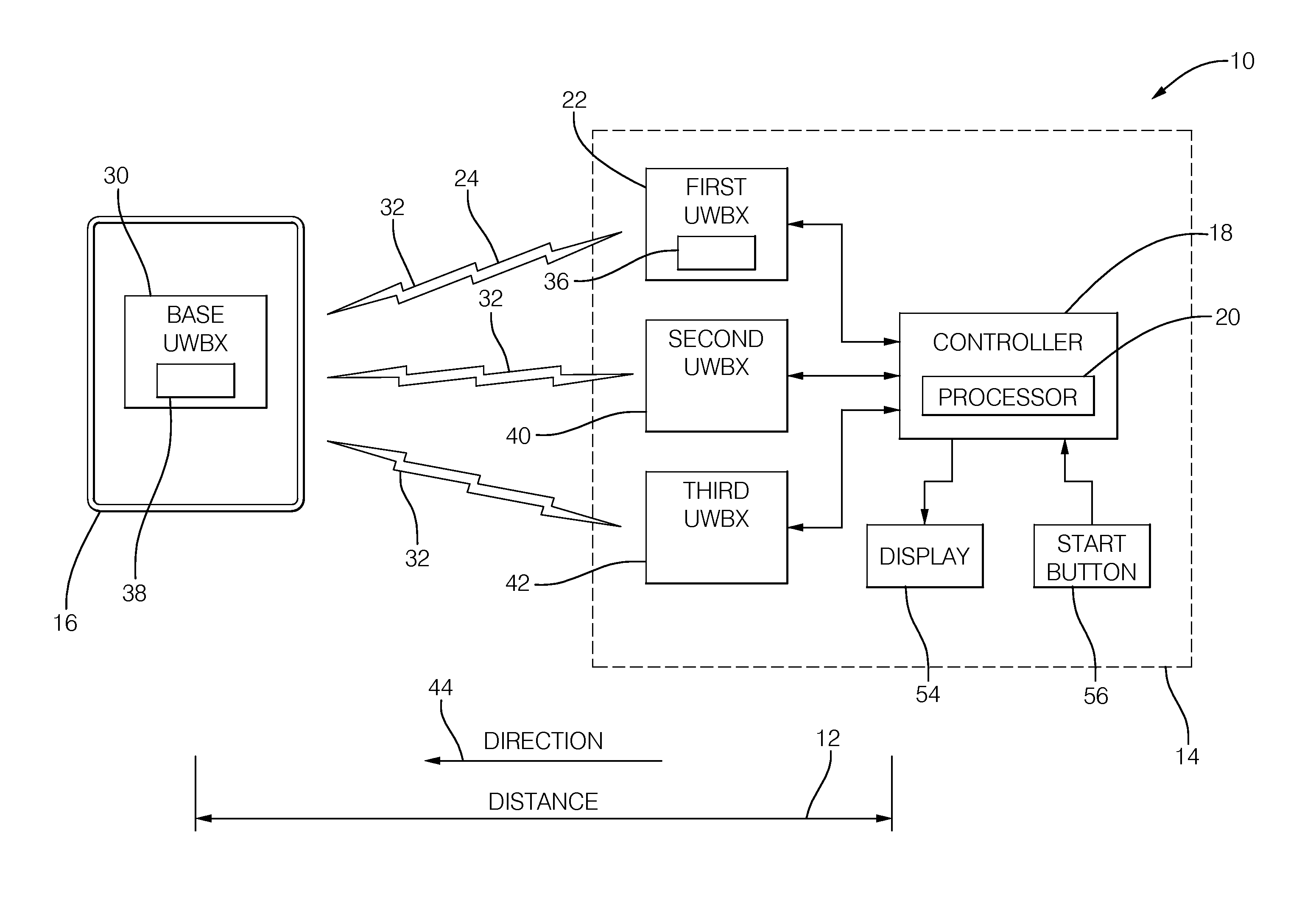
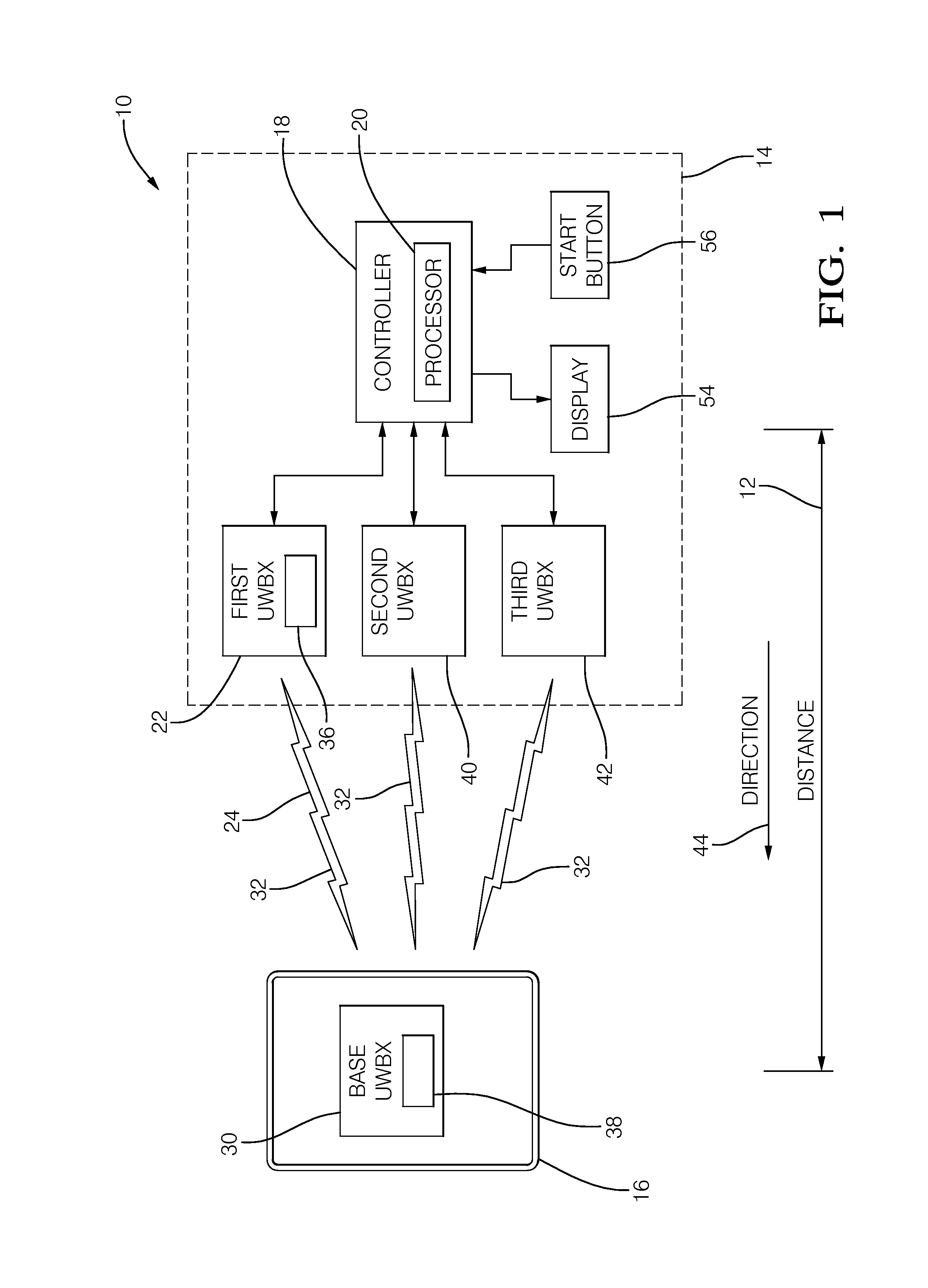
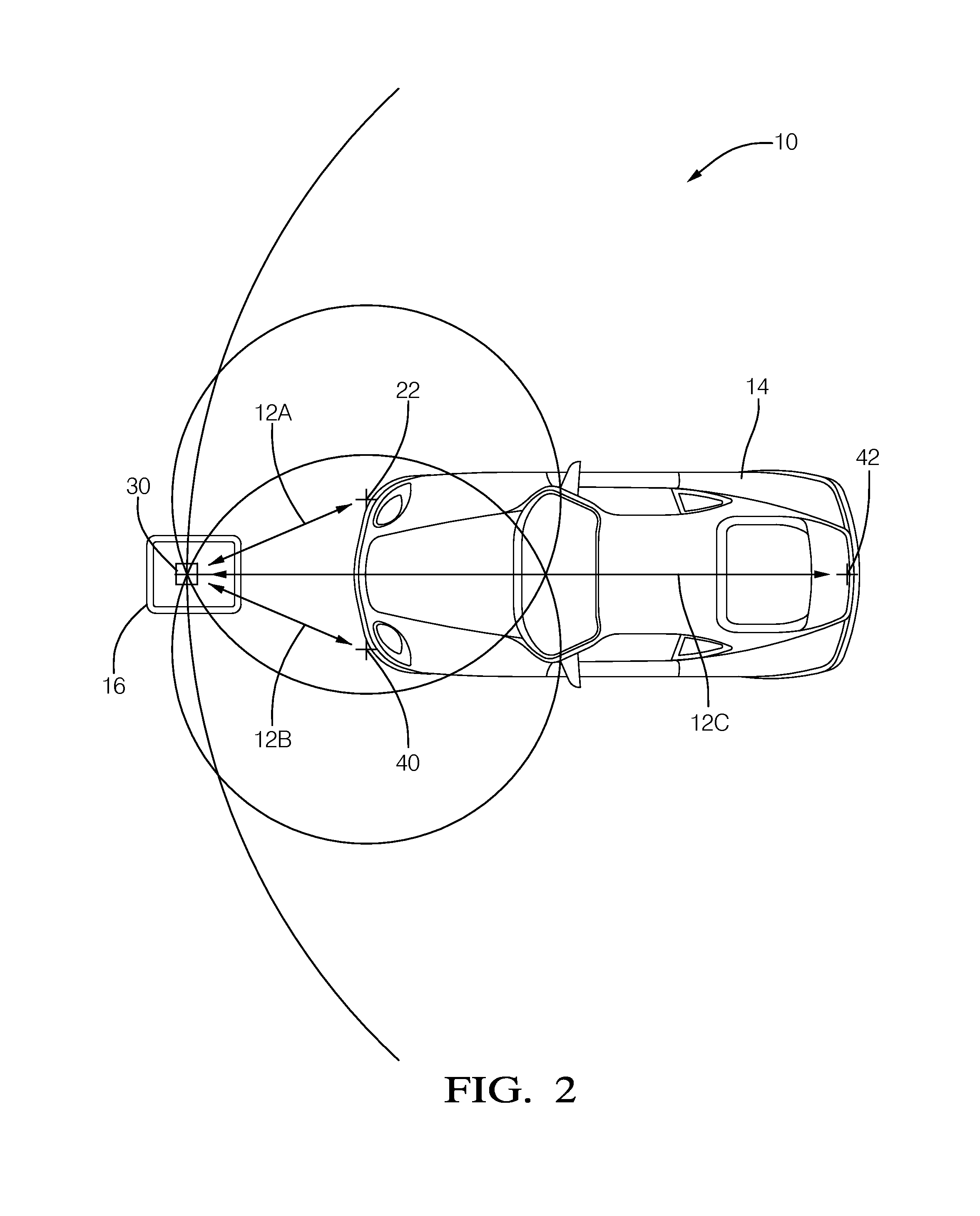
[0015]FIG. 1 illustrates a non-limiting example of a system 10 for positioning a vehicle 14 over a wireless charging station 16. As will become apparent in the description that follows, the system 10 is generally configured to determine a distance 12 and / or a direction 44 (i.e. relative distance and / or relative direction) between the vehicle 14 and the wireless charging station 16. Other alternative configurations or embodiments of the system 10 are presented following the description of the example shown in FIG. 1. the vehicle 14 may be an automobile, truck, utility vehicle, or any type of vehicle that relies on batteries all or in-part for propulsion. The wireless charging station 16 may be comparable to what is shown in U.S. Pat. No. 8,008,888 issued Aug. 30, 2011 to Oyobe et al.

[0016]In this example, the wireless charging station 16 is equipped with a base wideband transceiver (UWBX) 30, and the vehicle 14 is equipped with a first UWBX 22 and a second UWBX 40. In general, the fi...


PUM


Abstract

A system for positioning a vehicle over a wireless charging station. The system includes a plurality of ultra wideband transceivers (UWBX) installed on the vehicle and the wireless charging station, and a controller configured to determine various distances between the various UWBXs.

Description

TECHNICAL FIELD OF INVENTION[0001]This disclosure generally relates to wireless charging of electric or hybrid vehicles, and more particularly relates to using ultra wideband transceivers (UWBX) to assist with positioning a vehicle over a wireless charging station.BACKGROUND OF INVENTION[0002]Electric vehicles and electric-hybrid vehicles are gaining in popularity with consumers. The electric motors in these vehicles are typically powered from multiple storage batteries disposed in a battery pack in the vehicle. If the battery needs to be recharged while the vehicle is parked, a plug or leaded charge-coupling device is connected to the vehicle, typically by the vehicle operator. However, some operators object to having to ‘plug-in’ their vehicle each time the vehicle is parked.[0003]Wireless or connector less battery chargers have been proposed, see U.S. Pat. No. 5,498,948 issued Mar. 12, 1996 to Bruni et al., and U.S. Pat. No. 8,008,888 issued Aug. 30, 2011 to Oyobe et al. A wirele...

Claims


Application Information

Patent Timeline
Patent Type & Authority Patents(United States)
IPC IPC(8): H02J7/00G01R29/00B60L11/18
CPCB60L11/1829B60L11/182B60L11/1825G01R29/00B60L2230/16B60L53/126B60L53/305B60L53/31B60L53/38Y02T10/70Y02T10/7072Y02T90/12Y02T90/14Y02T90/16
Inventor OMAN, TODD P.HAWES, KEVIN J.
Owner APTIV TECH LTD
Why Eureka
Try Eureka