Thermoelectric generator of vehicle

a technology of thermoelectric generator and vehicle, which is applied in the direction of generator/motor, machine/engine, mechanical apparatus, etc., can solve the problems of low thermoelectric efficiency of thermoelectric generator, deterioration of the thermoelectric efficiency of the thermoelectric generator, so as to reduce manufacturing costs, reduce the number of parts, and simple structure

Active Publication Date: 2015-08-25
HYUNDAI MOTOR CO LTD +2
View PDF4 Cites 0 Cited by
  • Summary
  • Abstract
  • Description
  • Claims
  • Application Information

AI Technical Summary

Benefits of technology

[0013]Accordingly, the present invention attempts to solve the problems of the related art and provides a thermoelectric generator of a vehicle which is small and has improved thermoelectric generation efficiency.
[0022]Since a structure is simple and the number of parts is small, a manufacturing cost is reduced and productivity is improved.
[0023]The size of the thermoelectric generator of the vehicle of the present invention is small, and as a result, the thermoelectric generator is easily mounted on a vehicle package and can be applied to various vehicles.
[0024]A heat-exchange mesh may be installed between the high-temperature part and the thermoelectric module to increase the contact dimension with the exhaust gas, and as a result, the thermal energy of the exhaust gas is more efficiently transferred to the thermoelectric module and noise of the exhaust gas passing through the thermoelectric module is also reduced.

Problems solved by technology

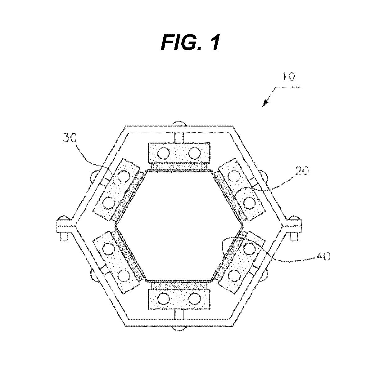
However, in the thermoelectric generator of the vehicle in the related art, since the thermal energy of the exhaust gas is not sufficiently transferred to a high-temperature part, a recovery ability of the thermal energy of the exhaust gas deteriorates, and as a result, thermoelectric efficiency of the thermoelectric generator deteriorates.
Further, the thermoelectric generator of the vehicle in the related art is low in thermoelectric generation efficiency compared to a size thereof because a heat exchange dimension is small, and thus a heat transfer rate is low, even though the cooling device 30 occupies a large dimension.

Method used


Image

  • Thermoelectric generator of vehicle
  • Thermoelectric generator of vehicle
  • Thermoelectric generator of vehicle

Examples


Embodiment Construction

[0033]Reference will now be made in detail to various embodiments of the present invention(s), examples of which are illustrated in the accompanying drawings and described below. While the invention(s) will be described in conjunction with exemplary embodiments, it will be understood that present description is not intended to limit the invention(s) to those exemplary embodiments. On the contrary, the invention(s) is / are intended to cover not only the exemplary embodiments, but also various alternatives, modifications, equivalents and other embodiments, which may be included within the spirit and scope of the invention as defined by the appended claims.

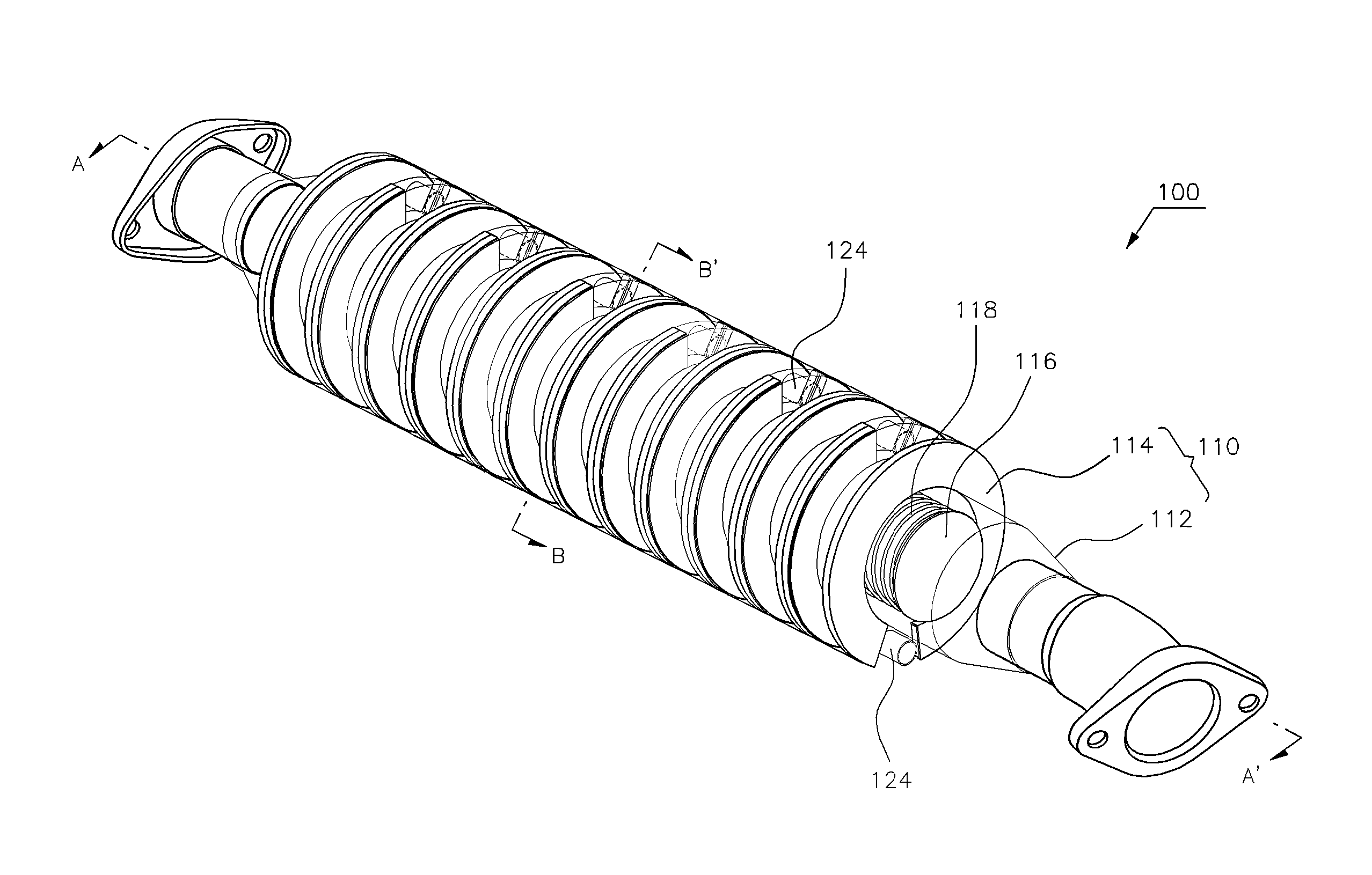
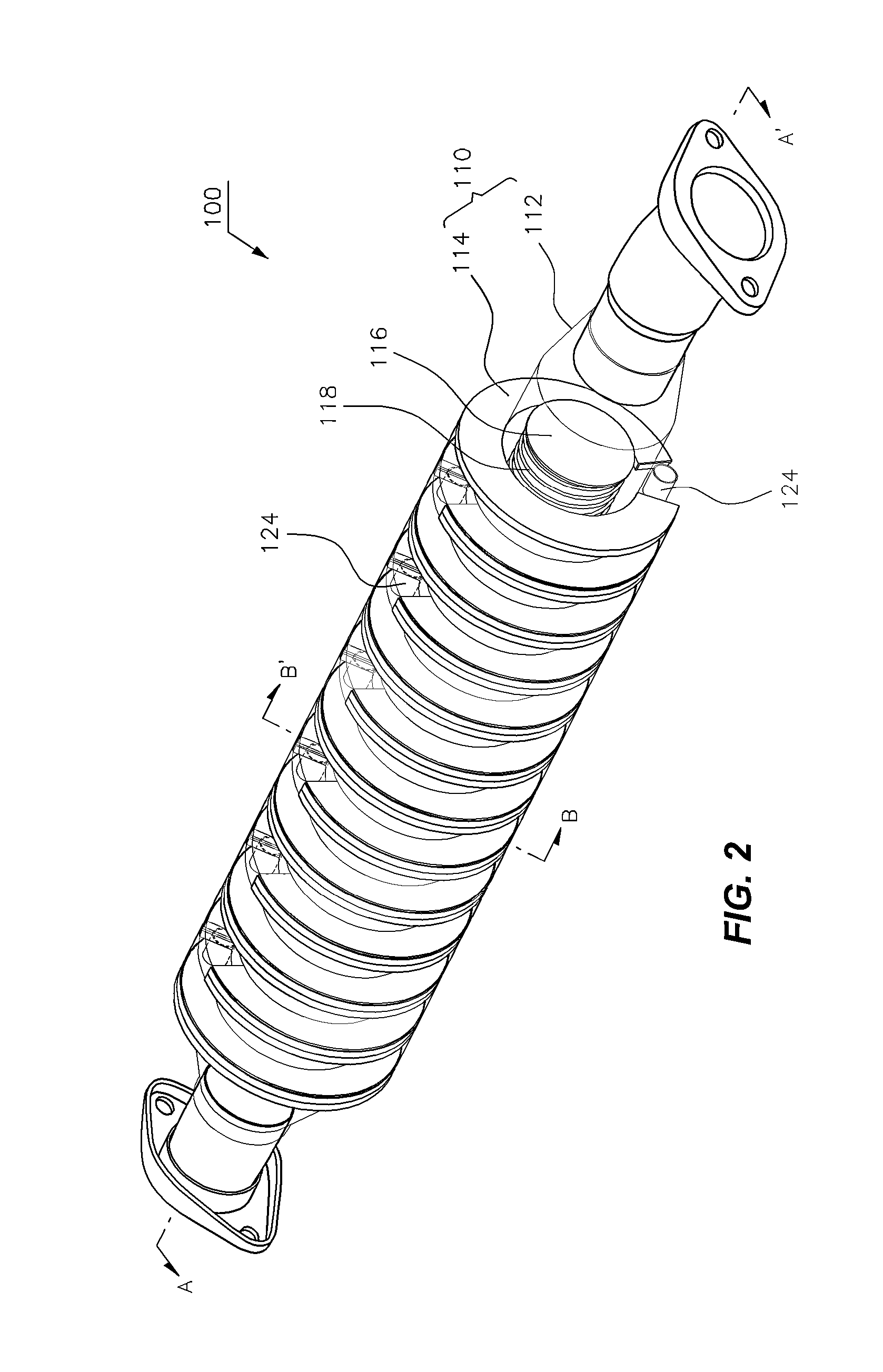
[0034]FIG. 2 is a perspective view illustrating a thermoelectric generator of a vehicle according to various embodiments of the present invention. FIG. 3 is an exploded perspective view of a high-temperature part, a thermoelectric module, and a low-temperature part of the thermoelectric generator of the vehicle according to various em...


PUM


Abstract

A thermoelectric generator of a vehicle converts thermal energy of exhaust gas of an engine into electric energy by using a thermoelectric phenomenon, and may include: a high-temperature part heated by exchange heat and a plurality of pairs of heat transfer plates mounted on an outer peripheral surface of an exhaust pipe at a predetermined interval; pairs of thermoelectric modules acquired by bonding a P-type semiconductor and an N-type semiconductor, interposed between the pairs of heat transfer plates to generate electricity, and electrically connected to each other; and a low-temperature part interposed between the pairs of thermoelectric modules and cooling inner surfaces of the pairs of thermoelectric modules. The plurality of thermoelectric modules generates electricity by a difference in temperature between heated outer surfaces and cooled inner surfaces. Thermoelectric efficiency is improved and a small-sized thermoelectric generator of a vehicle may be implemented.

Description

CROSS-REFERENCE TO RELATED APPLICATIONS[0001]The present application claims priority of Korean Patent Application Number 10-2011-141320 filed Dec. 23, 2011, the entire contents of which application is incorporated herein for all purposes by this reference.BACKGROUND OF INVENTION[0002]1. Field of Invention[0003]The present invention relates to a thermoelectric generator, and more particularly, to a thermoelectric generator of a vehicle that generates power by using heat of exhaust gas of the vehicle.[0004]2. Description of Related Art[0005]A thermoelectric element refers to an element using a thermoelectric phenomenon in which a difference in temperature between both ends of the element is converted into electricity to convert thermal energy into electric energy or the difference in temperature between both ends of the element is caused by making electricity flow on the element to convert the electric energy into the thermal energy. The thermoelectric element is used in a small-scale...

Claims


Application Information

Patent Timeline
Patent Type & Authority Patents(United States)
IPC IPC(8): H01L35/30F01N5/02H01L35/32
CPCF01N5/025H01L35/32Y02T10/16Y02T10/12H10N10/17H02N3/00H10N15/00
Inventor AN, HO-CHANSEON, JONG-HOSEO, HO-CHEOLJANG, SUNG-OOL
Owner HYUNDAI MOTOR CO LTD
Why Eureka
Try Eureka