
Respiratory system

a technology of respirator and airway, applied in the field of respirator, can solve the problems of insufficient heat and moisture in the airway, condensation of breathable gas, and high potential side effects, and achieve the effect of reducing overheating

Active Publication Date: 2015-09-01
PLASTIFLEX GRP NV
View PDF47 Cites 29 Cited by
  • Summary
  • Abstract
  • Description
  • Claims
  • Application Information

AI Technical Summary

Benefits of technology

The invention aims to provide a heating element that can detect and prevent overheating in a conduit. The technical effect is to improve the safety and reliability of the heating process.

Problems solved by technology

However, as soon as the respiratory care treatment has started, potential side effects often arise which are not due to the original root cause for which the external respiratory assistance was needed in the first place.
Due to the high air flow rates, the airways are not able to deliver sufficient heat and moisture.
As the heated and humidifier air travels along the conduit, some heat is lost to the air outside of the conduit resulting in condensation of the breathable gas.
The use of additional separate sensors is not always desired.
A problem with PTC materials is that upon overheating they melt down.
So overheating of the resistance, which may occur, causes permanent damage and the whole conduit has to be replaced.
However, tests prove that neither of the tested humidifier systems, when operated under normal ambient conditions, i.e. normal ambient temperature, or challenged ambient conditions, i.e. low ambient temperature, are able to deliver the required optimal setting for temperature and humidity but stay well below this optimal setting.
However, the maximum temperature of the humidification chamber is restricted since, at too high temperatures, the air flow will contain a too high amount of moisture that, once passing through the outlet hose and being cooled down by ambient temperature, will start to condensate in the outlet hose, i.e. the hose connecting the humidifier system and the patient interface.
Condensation is a very undesirable phenomenon in ventilation and CPAP therapy.
However, due to the heating relative humidity dropped and more importantly, the machine was not able to deliver the optimum absolute humidity of 30 mg water / liter air necessary to maximize patient comfort.
This drills down to the basic property of a humidifier system that, in essence, was not able to deliver sufficient absolute humidity to the air flow coming into the reservoir due to the restricted maximum temperature.
Due to the restricted maximum temperature, the water bath can transfer a limited amount of humidity depending on the heat capacity of the water at that maximum temperature.
As such, this cold air will extract energy from the heated humidifier, thereby reducing its efficiency to maximize humidity uptake in the humidifier and thereby reducing the dewpoint of the outlet air.
A reduced dewpoint means less absolute humidity so less comfort for the patient.
In particular, the heated outlet hose does help to maintain or increase temperature of the air flow coming out of the humidifier chamber, thereby contributing to reducing the risk for condensation, but the heated hose does not contribute to increasing the absolute humidity of the airflow delivered to the patient.
As a consequence, even the F&P benchmark 600 series with HH is not able to provide the 30 mg water / liter of air (as claimed in the product literature), especially in challenged conditions (cold ambient temperature).
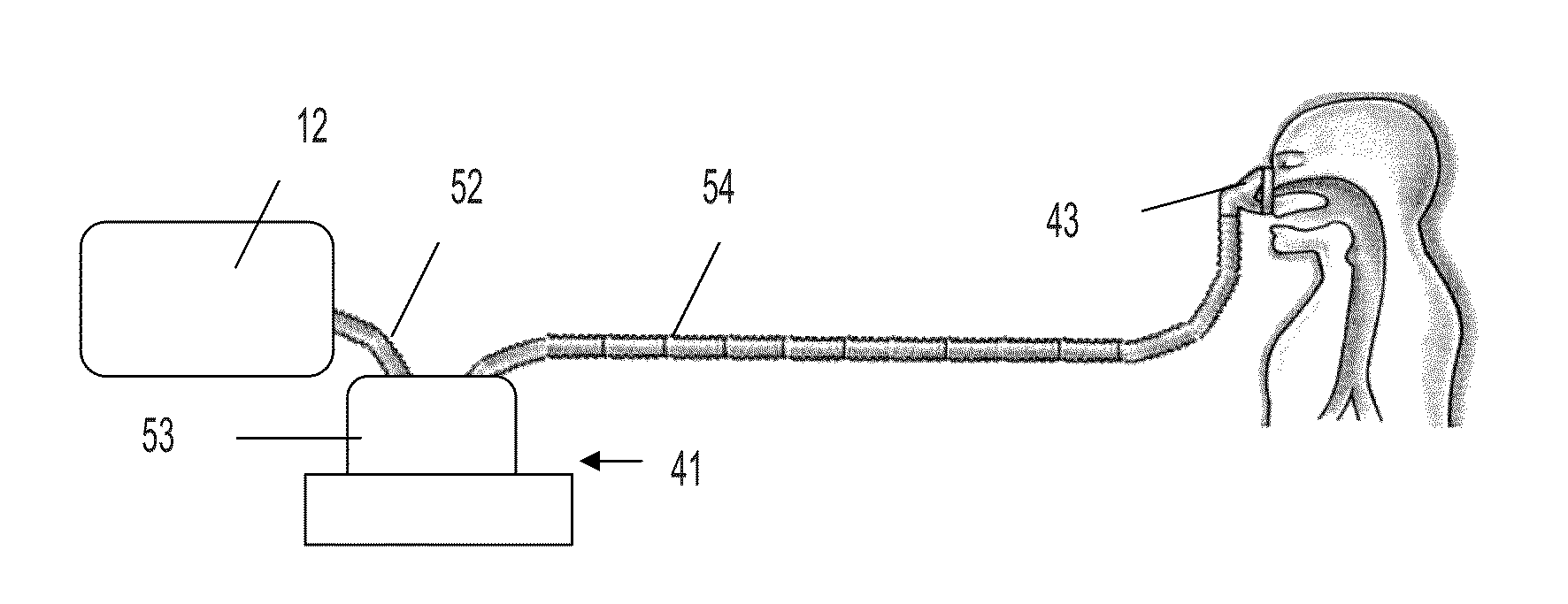
Another problem arises when heated and humidified air leaving the humidification chamber is passed through an inspiratory hose versus a respiratory mask.
However, because of the high amount of moisture of the air and because of the temperature difference between the ambient temperature and the temperature of the air delivered to the patient and the air breathed out by the patient, the air is likely to start to condensate in the hoses and the respiratory mask.
The mask is however exposed to the highest concentration of moisture and greatest temperature differences and thus has the highest risk to the occurrence of condensation.
Another problem with current respiratory systems is that they are very costly.
This results in very high replacement costs for the patient.
Moreover, the current respiratory systems offer few flexibility to the patient.
Because most of the parts are fixedly attached to one another, it is difficult to upgrade the system once therapy has started.
Another problem is that the patient is not able to adjust the settings, within clinical limits, such that the most comfortable conditions are achieved from a patient's perspective.
However, because ambient conditions may be different at home compared to clinical conditions, the same results are not always achieved at home.
Unless the humidified gas is kept above its dewpoint by using for example a heated wire breathing circuit, the gas will cool and the water vapor will be lost as condensation.

Method used


Image

  • Respiratory system
  • Respiratory system
  • Respiratory system

Examples


experiment 1

Air flow: 10

[0211]

HeatingHeattingT ambient = 13-14° C.Setting Inlet Outlet Other Td ambient = 9-9.5° C.HHHosehosemofificationsT wTTd19offon4525.418.329onon4525.921.439ononwith plug in4528.324.445ononwith plug in38.627.121.6

Line 1-Line 2: Effect of Heating the Inlet Air:

[0212]When the inlet air was not heated, the dewpoint of the outlet air is 18.3° C. (equivalent to 15.6 mg water / liter air). With the heating system in the inlet hose on, the dewpoint is increased to 21.4° C. or 18.7 mg / l. This is an increase of 20% in vapor content. Note that heating the inlet air does not have a significant effect on the outlet air temperature.

Line 2-Line 3: Effect of Air Turbulence on Water Surface

[0213]A plug was mounted on the inlet on the inside of the HH in order to create turbulence on the water surface in the reservoir. The plug is also expected to have an effect on the air flow speed (air flow reduction).

[0214]As a result of mounting the plug, another 3° C. dewpoint increase was noticed. The...

experiment 2

Air flow: 10

[0219]

HeatingHeattingT ambient = 13-14° C.SettingInlet Outlet Other Td ambient = 9-9.5° C.HHHosehosemofificationsTwTTd9onon4834.722.29ononwith baffles4835.825.29ononwith plug + baffles4836.531.3

[0220]Confirmation of Effect of Increased Residence Time and Water Surface Turbulence:

[0221]Two baffles were introduced in the HH to force the air to circulate over the heated water surface: increase in dewpoint of 3° C. Adding the plug (restricted air flow+turbulence on water surface) resulted in another 6° C. increase in dewpoint.

experiment 3

Air flow: 10

[0222]

HeatingHeattingT ambient = 23° C.SettingInlet Outlet Other Td ambient = 9-10° C.HHHosehosemofificationsTwTTd9offoffwith baffles4829.3229onoffwith baffles4829.2239ononwith baffles4836.222.9

[0223]Confirmation of effect of heated inlet air: dewpoint increase of 1° C. This increase is significant but less explicit when compared to more extreme ambient temperature of 13-14° C.

[0224]Very obvious effect of heating the outlet air in the outlet hose: temperature increased with 7° C.


PUM

PropertyMeasurementUnit
temperatureaaaaaaaaaa
temperaturesaaaaaaaaaa

Abstract

A modular respiratory system to which different parts can be added in a convenient way enabling such upgraded respiratory system to deliver the most comfortable respiratory conditions at an acceptable cost of ownership.

Description

FIELD OF THE INVENTION[0001]The present invention relates to a respiratory system for enhancing respiratory care patient comfort and compliance. The respiratory apparatus of the present invention can be used for humans as well as for veterinary purposes.DESCRIPTION OF RELATED ART[0002]During respiratory care treatments a respiratory gas is delivered to the patient. However, as soon as the respiratory care treatment has started, potential side effects often arise which are not due to the original root cause for which the external respiratory assistance was needed in the first place.[0003]As an example, but not limited to, serves the case of a patient which is diagnosed with Obstructive Sleep Apnoea (OSA). In OSA patients, the tongue and uvula partly or completely block air from moving down the throat to the lungs. During Continuous Positive Airway Pressure (CPAP) treatment an air flow is delivered to the patient, allowing air to pass down the throat of the patient to the lungs. Due t...

Claims


Application Information

Patent Timeline
Patent Type & Authority Patents(United States)
IPC IPC(8): A61M16/06A61M16/10A61M16/08A61M16/16F16L53/00H05B3/58A61M16/00F16L53/38
CPCA61M16/1075A61M16/06A61M16/0816A61M16/0875A61M16/108A61M16/109A61M16/1095A61M16/16A61M16/161F16L53/008H05B3/58A61M2016/0027A61M2016/0039A61M2016/103A61M2016/1025A61M2205/3368A61M2205/3561A61M2205/3569A61M2205/3584A61M2205/3592A61M2205/3613A61M2205/3633A61M2205/3653A61M2205/502H05B2203/019H05B2203/02Y10T29/4998A61M16/0051A61M16/024F16L53/38
Inventor BEDFORD, JON RICHARDJAMES, MALCOLM GRAHAMKAYE, NEIL ANTHONYKURJA, JENOLANGEROCK, RIK JULIA RAOUL
Owner PLASTIFLEX GRP NV
Learn More