

Method and apparatus for manufacturing vehicle power transmission device
a technology for transmission devices and vehicles, applied in manufacturing tools, instruments, gearing, etc., can solve the problems of increasing the cost of vehicle power transmission devices, particularly prone to cracking of the lapping portion of weld beads, etc., and achieves low fracture ductility, easy and fast measurement, and low ductility.
- Summary
- Abstract
- Description
- Claims
- Application Information
AI Technical Summary
Benefits of technology
Problems solved by technology
Method used
Image

Examples
Embodiment Construction
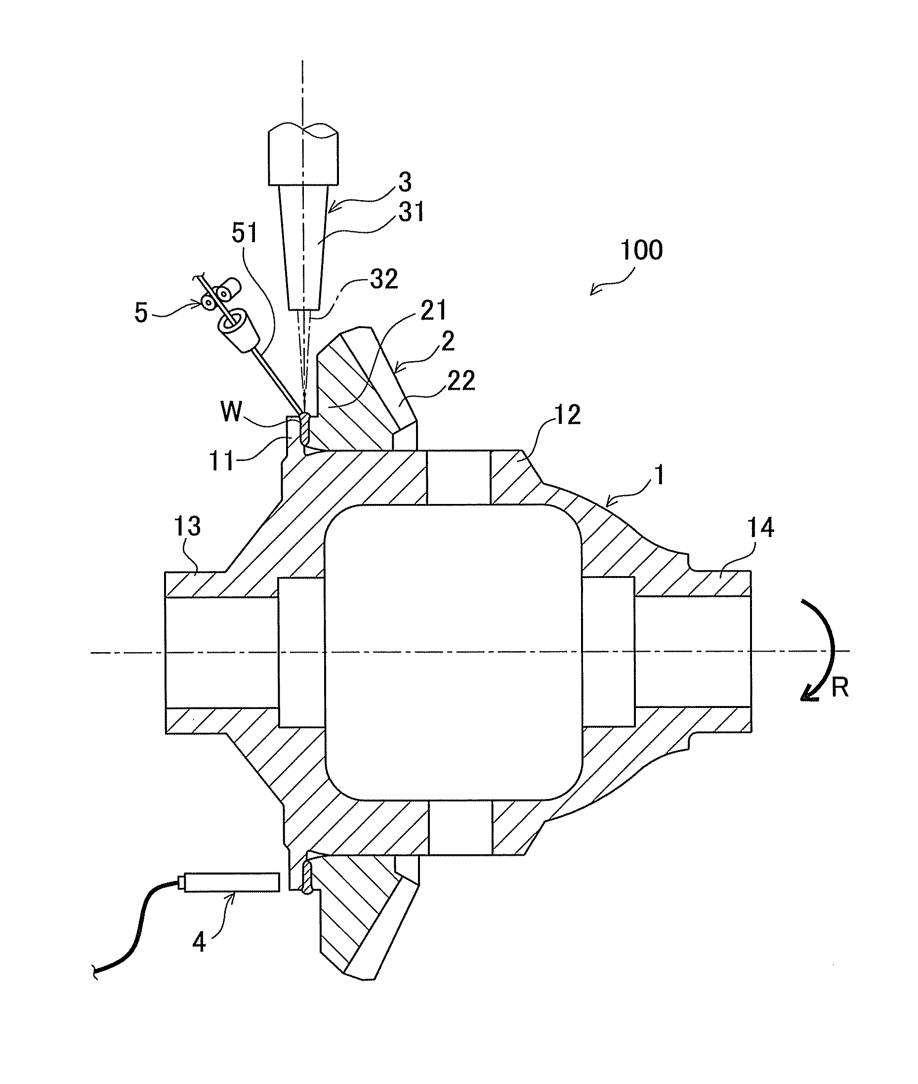
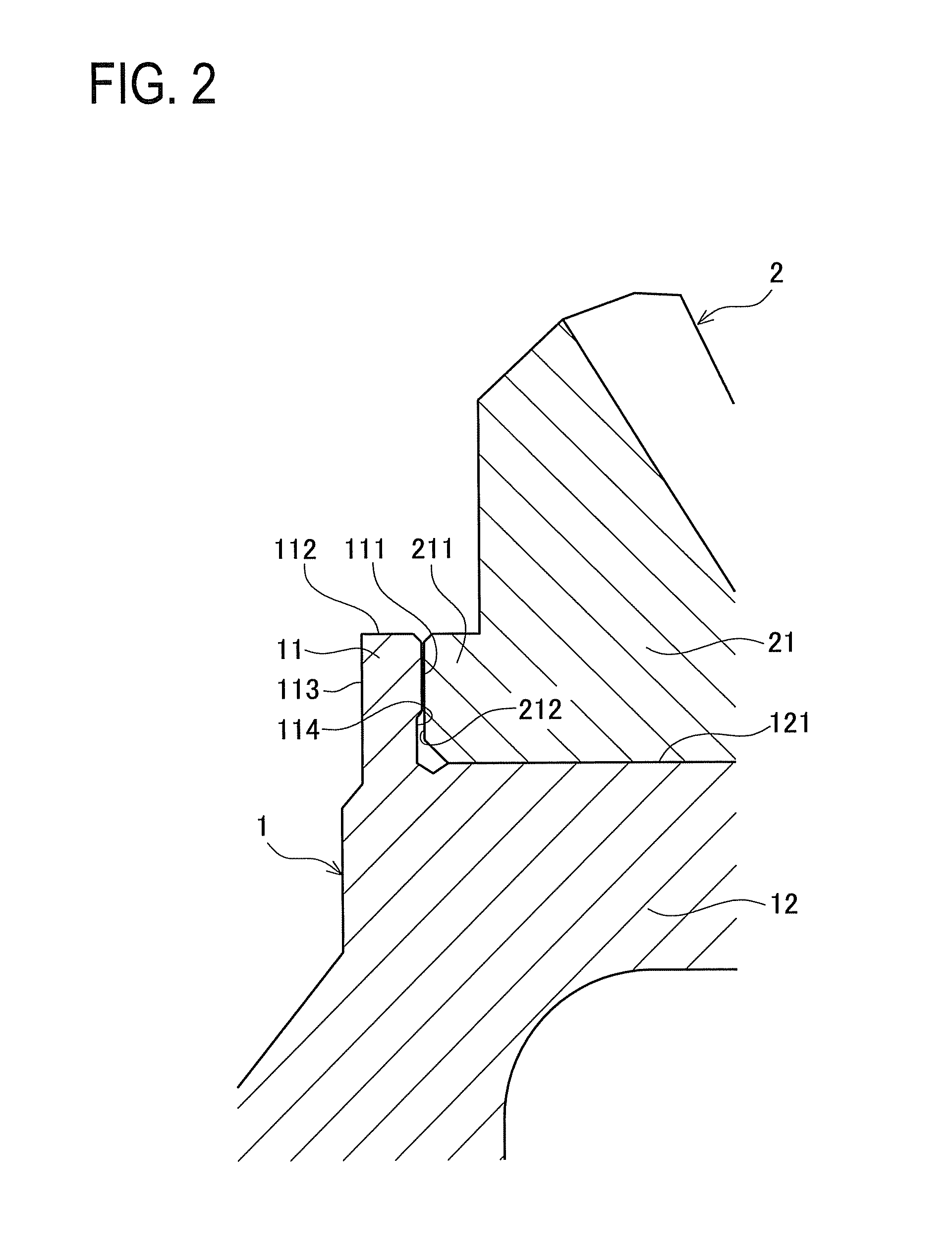
[0053]Next, an embodiment of a method and an apparatus for manufacturing a vehicle power transmission device according to the present invention will be described with reference to the accompanying drawings. The manufacturing method in this embodiment includes a welding step in which an annular flange is provided to stand on the outer peripheral surface of a differential case, and along an abutting portion between one side surface of the annular flange and a ring gear, butt-welding is performed such that ends of a weld bead are lapped; a measurement step of measuring an outline of the other side surface of the annular flange that is in close proximity to its one side surface, and an evaluation step of evaluating a weld condition based on part of the outline, which is measured in the measurement step, of a portion corresponding to the lapping portion of the weld bead. The structure of the abutting portion between the differential case and the ring gear will be described first, after w...
PUM
| Property | Measurement | Unit |
|---|---|---|
| thickness | aaaaa | aaaaa |
| penetration width | aaaaa | aaaaa |
| penetration width | aaaaa | aaaaa |
Abstract
Description
Claims
Application Information