Device for deblocking optical workpieces, in particular eyeglass lenses

a technology for optical workpieces and eyeglass lenses, applied in the field of eyeglass lenses, can solve the problems of very economic construction of devices and substantially increase the deblocking time, and achieve the effects of simple hardware, rapid deblocking process, and simple operation and operation safety

Active Publication Date: 2015-09-01
SATISLOH AG
View PDF19 Cites 1 Cited by
  • Summary
  • Abstract
  • Description
  • Claims
  • Application Information

AI Technical Summary

Benefits of technology

[0014]Due to the fact that the high-pressure jet of pressure medium by contrast to the prior art defining the category no longer randomly impinges on the separating point between block piece and blocking material or the separating point between blocking material and workpiece, but as a consequence of the positionability of the nozzle with respect to the block piece can be targeted onto the respective separating point, it is possible to deblock the workpiece significantly more quickly, which renders the device according to the invention particularly suitable for use in RX workshops. In this regard, a rapid deblocking process can be beneficially operated with a relatively high pressure of the pressure medium without a risk of damage of the workpiece by the high-pressure jet of pressure medium, since through the selectively executable relative setting of nozzle and block piece or workpiece it is possible to avoid wiping of the high-pressure jet of pressure medium over the workpiece in a critical manner. Thus, it is possible to deblock workpieces, which are blocked in particular by adhesives, rapidly, safely and free of damage without requiring upstream soaking and / or softening processes and / or temperature-controlled pressure medium for the deblocking.
[0028]It is further preferred if a withdrawal device with a suction head is provided, which for the deblocking can be acted on by a sub-atmospheric pressure in order to firmly suck against a second optically effective surface, which is remote from the block piece, of the workpiece so that a defined withdrawal force can be applied to the workpiece by the withdrawal device via the suction head. On the one hand, this is beneficial for a rapid deblocking process and on the other hand the workpiece during the deblocking is prevented from uncontrolled detaching or “flying off”, which could lead to damage of the workpiece.

Problems solved by technology

In this regard, CNC positionally regulated drives or the like—just as motors in general—are basically redundant, so that the device can be of very economic construction.
If the clear spacing is here too small, the blocking material is released only in the center of the fanned high-pressure jet; if, thereagainst, the clear spacing is selected to be too large, this substantially increases the deblocking time.

Method used


Image

  • Device for deblocking optical workpieces, in particular eyeglass lenses
  • Device for deblocking optical workpieces, in particular eyeglass lenses
  • Device for deblocking optical workpieces, in particular eyeglass lenses

Examples


Embodiment Construction

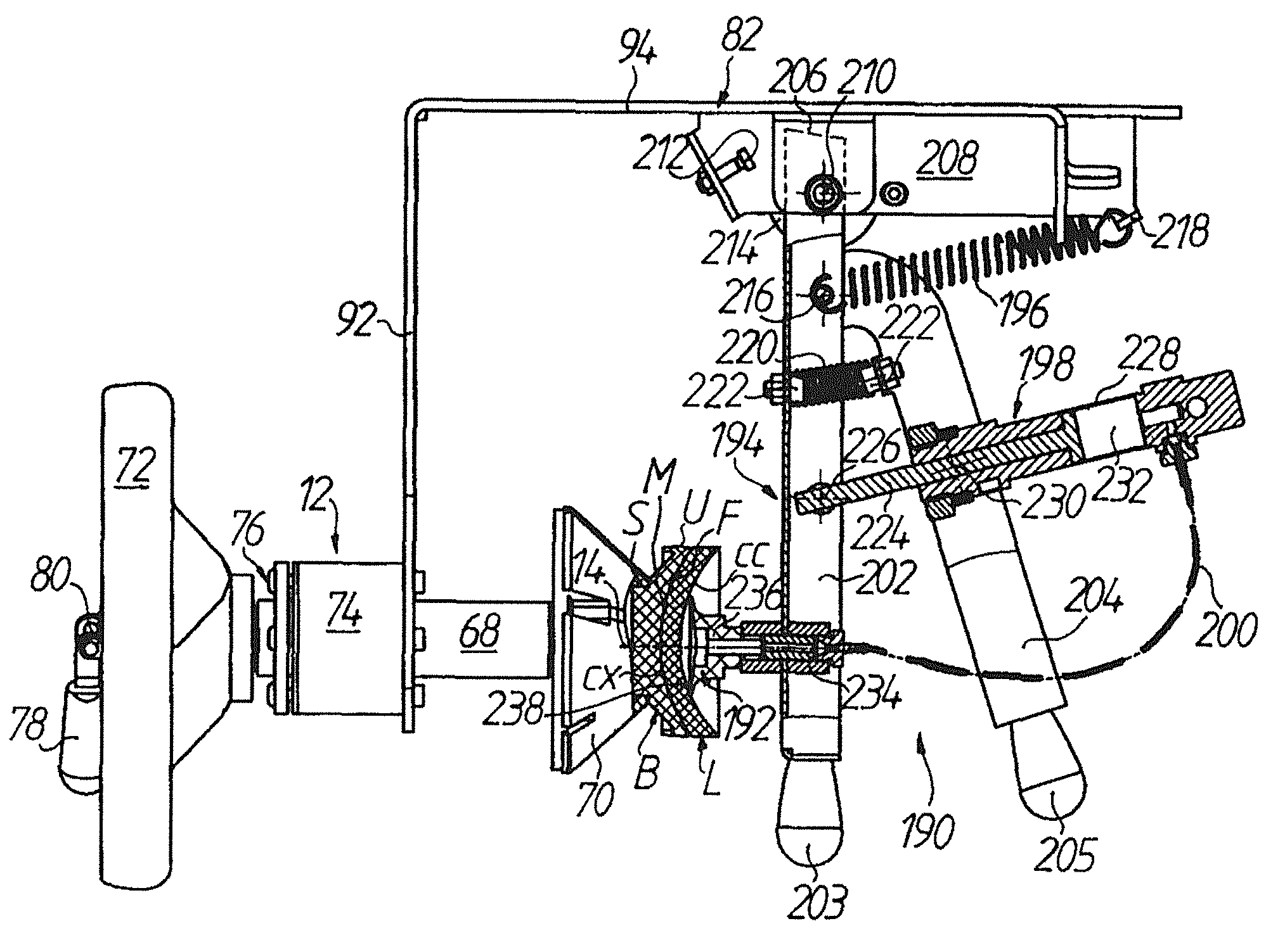
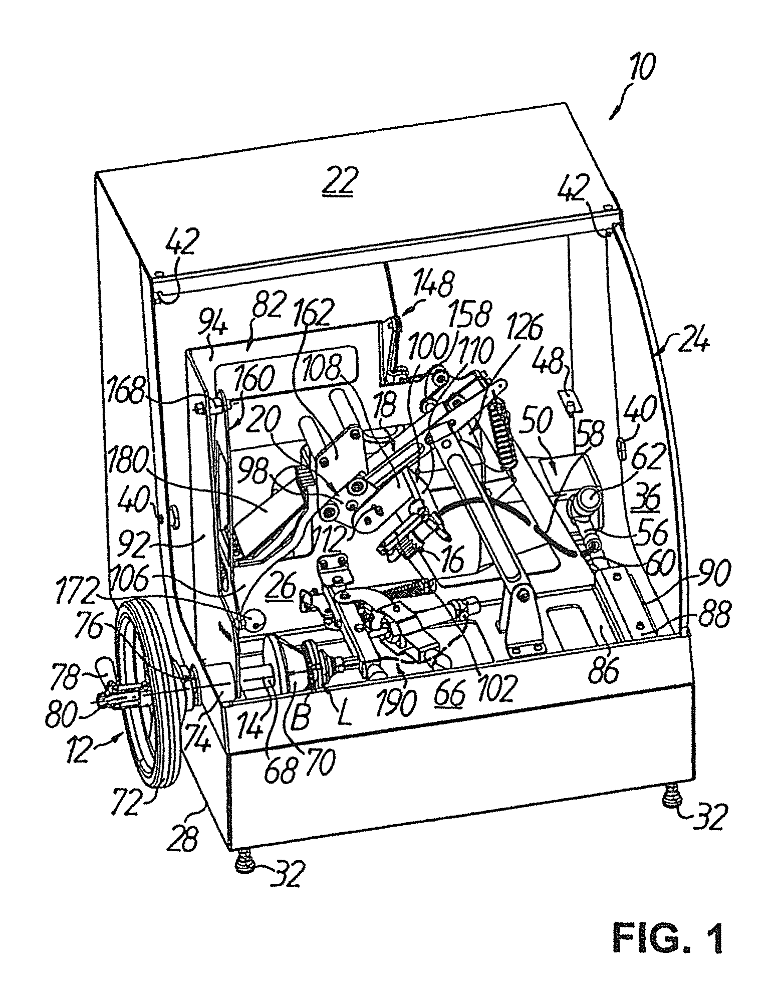
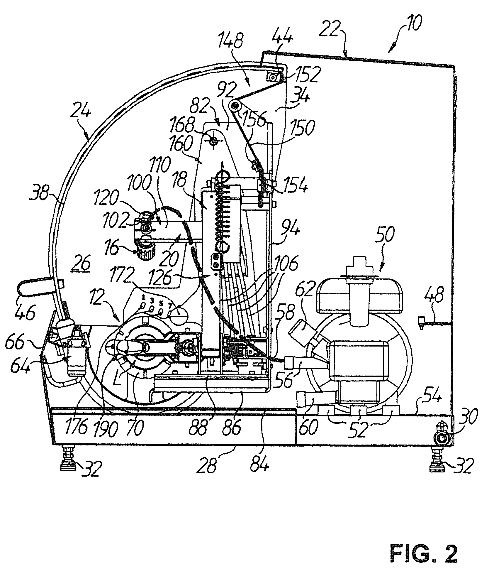
[0041]A device for deblocking spectacle lenses L as optical workpieces is denoted in the figures by 10. The deblocking device 10 comprises in general a first movement device 12 for rotation of a spectacle lens L, which is blocked on a block piece B, about a workpiece axis 14 of rotation, a nozzle 16 for delivery of a high-pressure jet H of pressure medium (see FIG. 6) in a direction substantially transverse to the workpiece axis 14 of rotation onto a point A of incidence in an edge region between block piece B and spectacle lens L, and a second movement device 18 for generating a relative movement between the nozzle 16 and the spectacle lens L. It is significant that the second movement device 18 has a nozzle guide section 20, at which the nozzle 16 is mounted and by which the nozzle 16 is positionable with respect to the block piece B under cam control in order to direct the high-pressure jet H of pressure medium in defined manner onto the point A of incidence, as will be described...


PUM

PropertyMeasurementUnit
temperatureaaaaaaaaaa
pressureaaaaaaaaaa

Abstract

A device for deblocking optical workpieces, having a first moving device for rotating a workpiece, which is blocked on a blocking piece, about a workpiece rotational axis and a nozzle for dispensing a pressurized stream in a direction that is essentially transverse to the workpiece rotational axis onto a point of incidence in an edge region between the blocking piece and the workpiece. The device also has a second moving device for generating a relative movement between the nozzle and the workpiece. The second moving device has a nozzle guiding portion on which the nozzle is mounted and by which the nozzle can be positioned with respect to the blocking piece in a cam-controlled manner in order to aim the pressurized stream towards the point of incidence in a defined manner.

Description

TECHNICAL FIELD[0001]The present invention relates generally to a device for deblocking optical workpieces.[0002]Generally termed “block mounting” or, for short, “blocking” in optical production is the procedure in which an optical workpiece is temporarily fastened by a suitable material (alloy with low melting temperature or adhesive) on a so-called “block piece” or, however, the blocking material is mounted on the workpiece so as to construct the block piece itself, which then serves the purpose of holding the workpiece in the respective processing machine and / or coating plant. A corresponding meaning attaches in optical production to the procedure of “deblocking” in which the optical workpiece after (final) processing thereof (at surface and / or edge) and / or coating is again separated from the block piece or blocking material.[0003]The invention particularly relates to a device for deblocking spectacle lenses. Spectacle lenses are blocked en masse in so-called “RX workshops” befor...

Claims


Application Information

Patent Timeline
Patent Type & Authority Patents(United States)
IPC IPC(8): B32B38/10B24B13/005
CPCB24B13/0057Y10T29/53
Inventor GEURTS, PETER JOHANNES LODEWIJKCOSTELLOE, NATHAN THOMAS
Owner SATISLOH AG
Why Eureka
Try Eureka