Eureka AIR delivers breakthrough ideas for toughest innovation challenges, trusted by R&D personnel around the world.

Dynamically stable pressure control system

Active Publication Date: 2015-09-08
SAUER DANFOSS NORDBERG
View PDF6 Cites 1 Cited by
  • Summary
  • Abstract
  • Description
  • Claims
  • Application Information

AI Technical Summary

Benefits of technology

The patent describes a hydraulic pressure control system that uses a pump to provide fluid to a motor. The pump has two circuits, with one circuit providing flow when needed and the other providing a steady flow. The second circuit has a valve that adjusts the pressure from the pump based on the load being sensed. There is also a flow control valve that compensates for any pressure drop in the system to improve its performance.

Problems solved by technology

Deficiencies in these prior art systems have been recognized.
Not only are these systems unstable, they have reduced dynamic performance.

Method used


Image

  • Dynamically stable pressure control system
  • Dynamically stable pressure control system
  • Dynamically stable pressure control system

Examples


Embodiment Construction

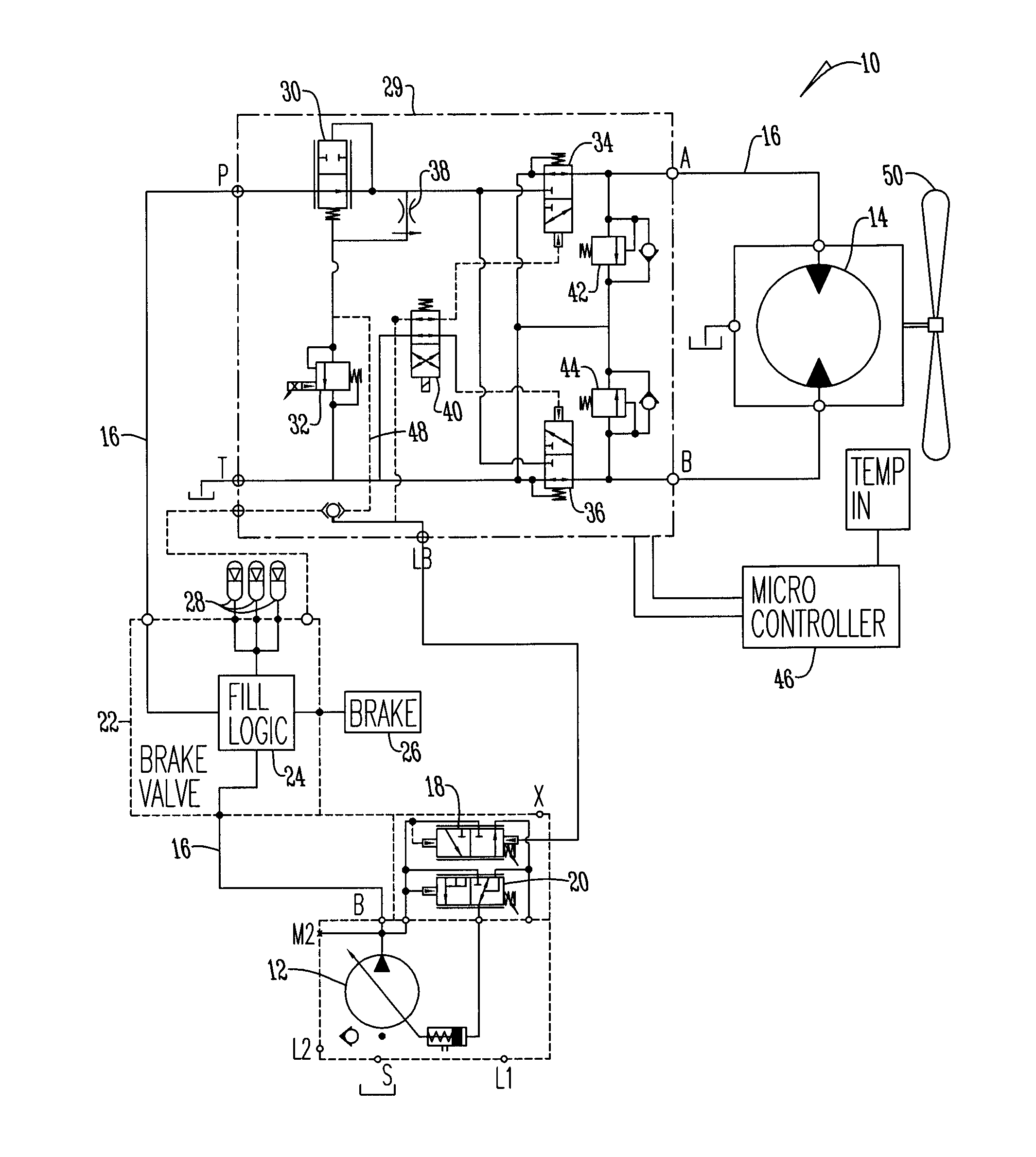
[0011]Referring to FIG. 3, the pressure control system 10 has a variable displacement pump 12 that is connected to a fixed displacement hydraulic motor 14 by fluid lines 16. The pump is also fluidly connected to pilot controlled pressure valves 18 and 20 and brake valve circuit 22. Brake valve circuit 22 includes fill logic 24 that is connected to brake 26 and accumulators 28.

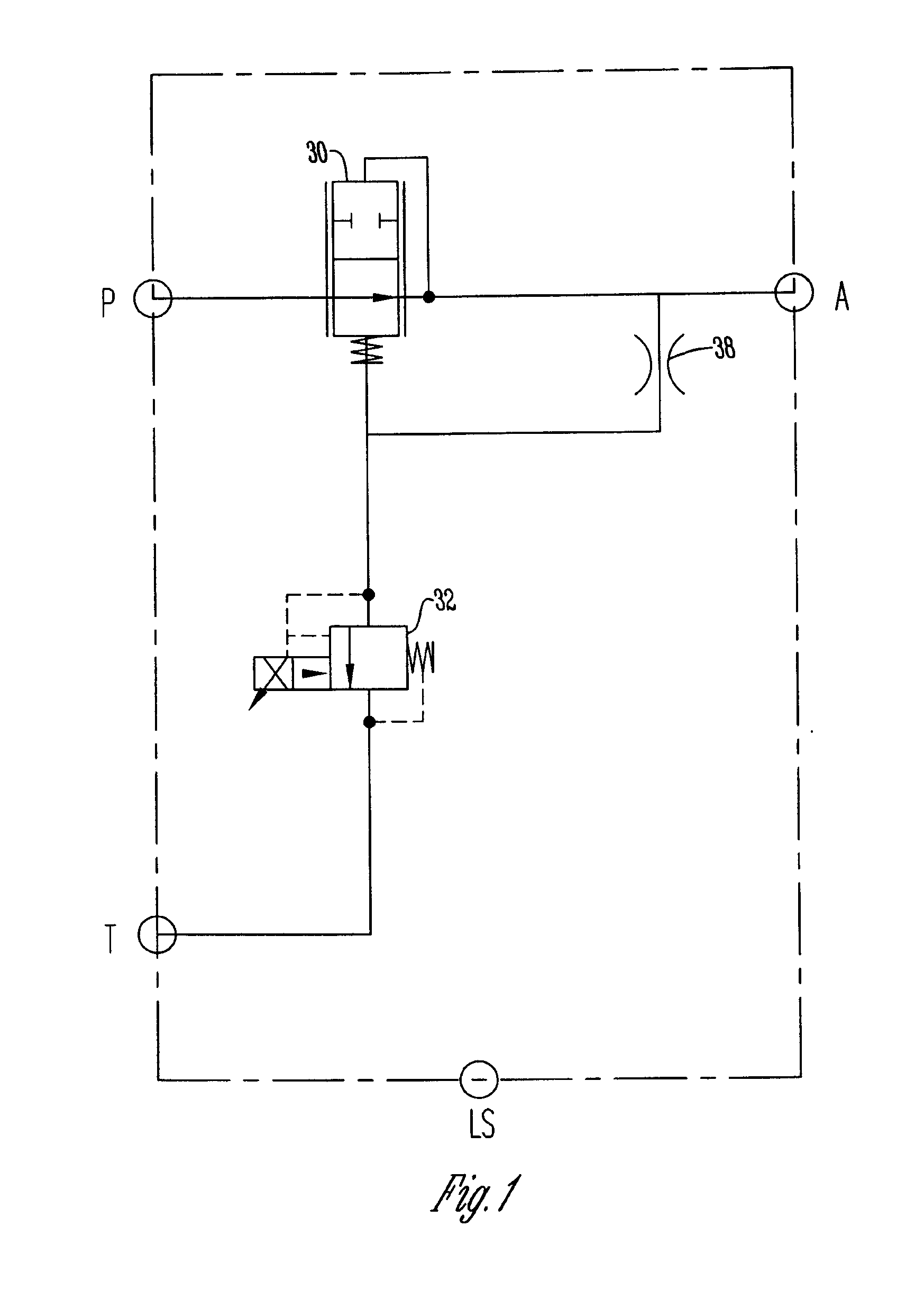
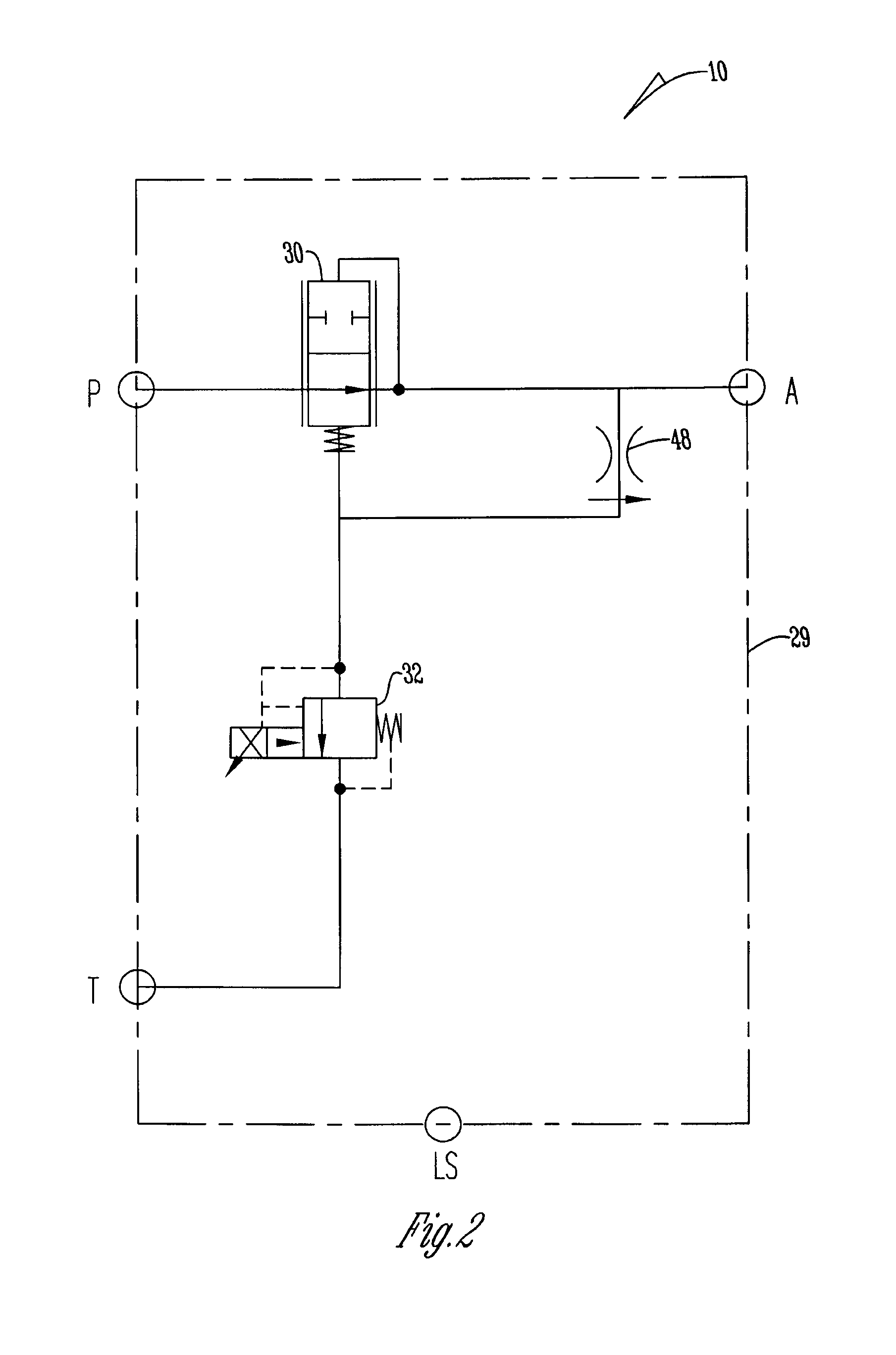
[0012]The brake valve circuit 22 is connected to a fan circuit 29 that includes pilot controlled pressure reducing valve 30 that is connected to proportional pressure relief valve 32, directional control valves 34 and 36 and active flow regulator valve 38. Flow valves 34 and 36 are connected to solenoid valve 40, shock / check valves 42 and 44, and motor 14. Motor 14 is connected to fan 50.

[0013]The electro proportional relief valve 32 and solenoid valve 40 are controlled by a micro controller 46. The micro controller 46 is also used to detect operational parameters of the hydraulic system 10. From these operatio...


PUM


Abstract

A hydraulic pressure control system having a variable displacement pump fluidly connected to a hydraulic motor. The pump provides flow to a first circuit upon demand. Remaining flow is provided to a second circuit. The second circuit includes a pilot controlled pressure reducing valve that adjusts the pumps outlet pressure based upon a sensed loads taken from a conduit between the pressure control valve and an active flow regulator valve.

Description

BACKGROUND OF THE INVENTION[0001]This invention relates to a hydraulic pressure control system and more particularly to a hydraulic pressure control system that produces a more consistent fluid flow rate.[0002]Well-known in the art is the use of a pilot controlled pressure reducing valve to control the pressure of a load in a hydraulic system. Also known in the art is the use of a flow control valve to control the hydraulic flow rate to the load. In these systems flow control is fundamentally different than pressure control. As shown in FIG. 1, the load signal line in prior art systems is connected directly to the load conduit to port A where the conduit connection from the load conduit to the pilot controlled pressure reducing valve incorporates a fixed orifice.[0003]Deficiencies in these prior art systems have been recognized. Not only are these systems unstable, they have reduced dynamic performance. Thus, a need exists in the art for a system that addresses these deficiencies.[0...

Claims


Application Information

Patent Timeline
IPC IPC(8): F15B11/16E02F9/22
CPCF15B11/162E02F9/226E02F9/2217E02F9/2296F16H61/4008F15B2211/50554F15B2211/5158F15B2211/7058
Inventor THROCKMORTON, CHARLES D.CROMER, STEPHEN D.MAHONY, GLENN M.STOLTENOW, MICHAEL J.DANIEL, CHAD J.
Owner SAUER DANFOSS NORDBERG
Why Eureka
Eureka Blog
Learn More