Elongated LED luminaire and associated methods

a technology of led luminaires and led lamps, applied in the field of light, can solve the problems of inability to connect fluorescent light fixtures directly to dimmer switches, inconvenient installation and operation of fluorescent lamps, and inability to meet the requirements of lighting and heating equipment, so as to reduce operating costs with respect to energy consumption, simple and inexpensive retrofit options, and avoid material waste

Inactive Publication Date: 2015-09-08
LIGHTING SCI GROUP
View PDF214 Cites 16 Cited by
  • Summary
  • Abstract
  • Description
  • Claims
  • Application Information

AI Technical Summary

Benefits of technology

[0013]With the above in mind, embodiments of the present invention are related to a luminaire adapted to be carried by a lighting fixture. The luminaire may be configured as a retrofit to engage mechanically and operationally with a conventional fluorescent light fixture. The luminaire may advantageously offer a simple and inexpensive retrofit option in terms of manufacturing, installation and maintenance. The design of the luminaire may deliver performance (e.g., brightness) that meets or exceeds the characteristics of a replaced fluorescent lamp, while avoiding the material waste inherent to prosthetic tube retrofit designs. The use of digital lighting technology, such as LEDs, in connection with the luminaire may advantageously provide decreased operating costs with respect to energy consumption. The LED-based technology may support tailoring of color temperature in ways not possible with standard fluorescent bulbs (e.g., color temperatures of 3000 Kelvin and below). The on-board power conditioning for LED-based lamps may provide for operation of the present invention using existing fluorescent light assembly circuitry and without requiring removal of fluorescent ballasts.

Problems solved by technology

However, fluorescent lamp technology has disadvantages.
A fluorescent lamp is typically more expensive to install and operate than an incandescent lamp because the fluorescent lamp requires a ballast to regulate the electrical current.
Fluorescent light fixtures cannot be connected directly to dimmer switches intended for incandescent lamps, but instead require a compatible dimming ballast.
The performance of fluorescent lamps may be negatively impacted by environmental conditions such as frequent switching and operating temperatures.
Many fluorescent lamps have poor color temperature, resulting in a less aesthetically pleasing light.
Also, if a fluorescent lamp that uses mercury vapor is broken, a small amount of mercury (classified as hazardous waste) can contaminate the surrounding environment.
Moreover, LEDs do not contain mercury.
However, a number of installation challenges and costs are associated with replacing linear fluorescent lamps with LED illumination devices.
The costs, which are similarly understood by those skilled in the art, typically stem from a need to replace or reconfigure a troffer or pendant fixture that is configured to support fluorescent lamps to instead support LEDs.
Consequently, employing LEDs to produce light distribution properties approximating or equaling the light dispersion properties of traditional lamps may require the costly and labor-intensive replacement or reconfiguration of the host light fixture, and / or the expensive and complexity-introducing design of LED-based solutions that minimize the installation impact to the host light fixture.
Often material and manufacturing costs are lost in this trade off.
Another challenge inherent to operating LEDs is heat.
LEDs suffer damage and decreased performance when operating in high-heat environments.
Moreover, when operating in a confined environment, the heat generated by an LED and its attending circuitry itself can cause damage to the LED.
However, heat sinks can sometimes negatively impact the light distribution properties of the light fixture, resulting in non-uniform distribution of light about the fixture.
Heat sink designs also may add to the weight and / or profile of an illumination device, thereby complicating installation, and also may limit available space for other components needed for delivering light.
Replacement of legacy lighting solutions may be complicated by the need to adapt LED-based devices to meet legacy form standards.
For example, in a commercial lighting system retrofit, disposal of a replaced fluorescent lamp's fixture housing often is impractical.
Also, power supply requirements of LED-based lighting systems can complicate installation of LEDs as a retrofit to existing light fixtures.
Too little current and voltage may result in little or no light.
Too much current and voltage can damage the light-emitting junction of the LED.
However, rather than maintain existing circuitry, the fixture is stripped not only of its fluorescent lamps but also of its wireway cover and ballast(s).

Method used


Image

  • Elongated LED luminaire and associated methods
  • Elongated LED luminaire and associated methods
  • Elongated LED luminaire and associated methods

Examples


Embodiment Construction

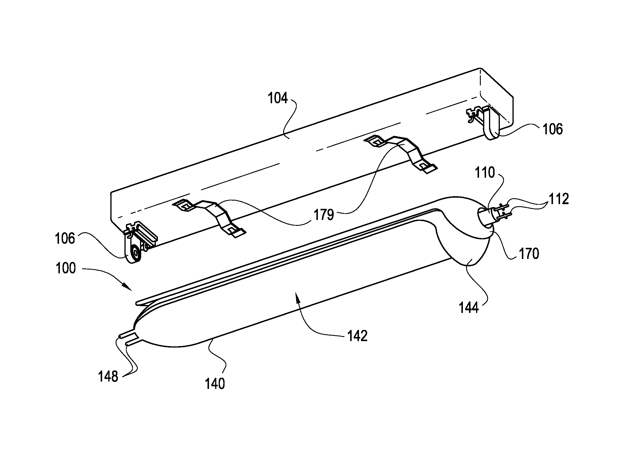
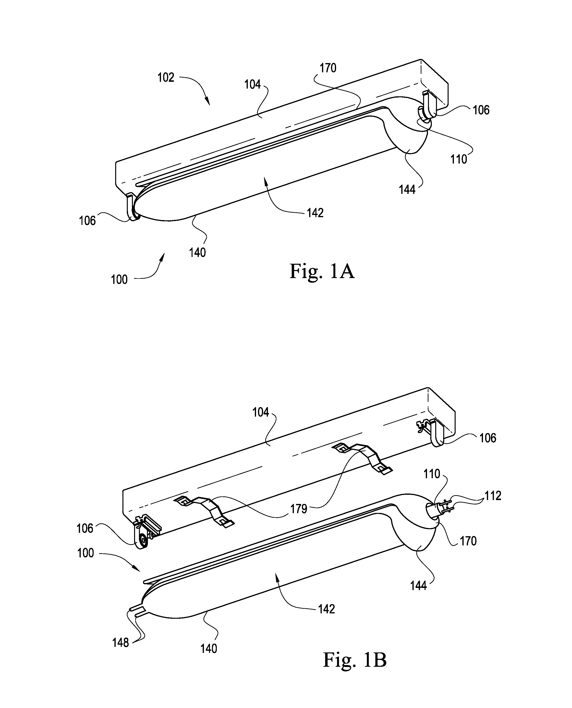
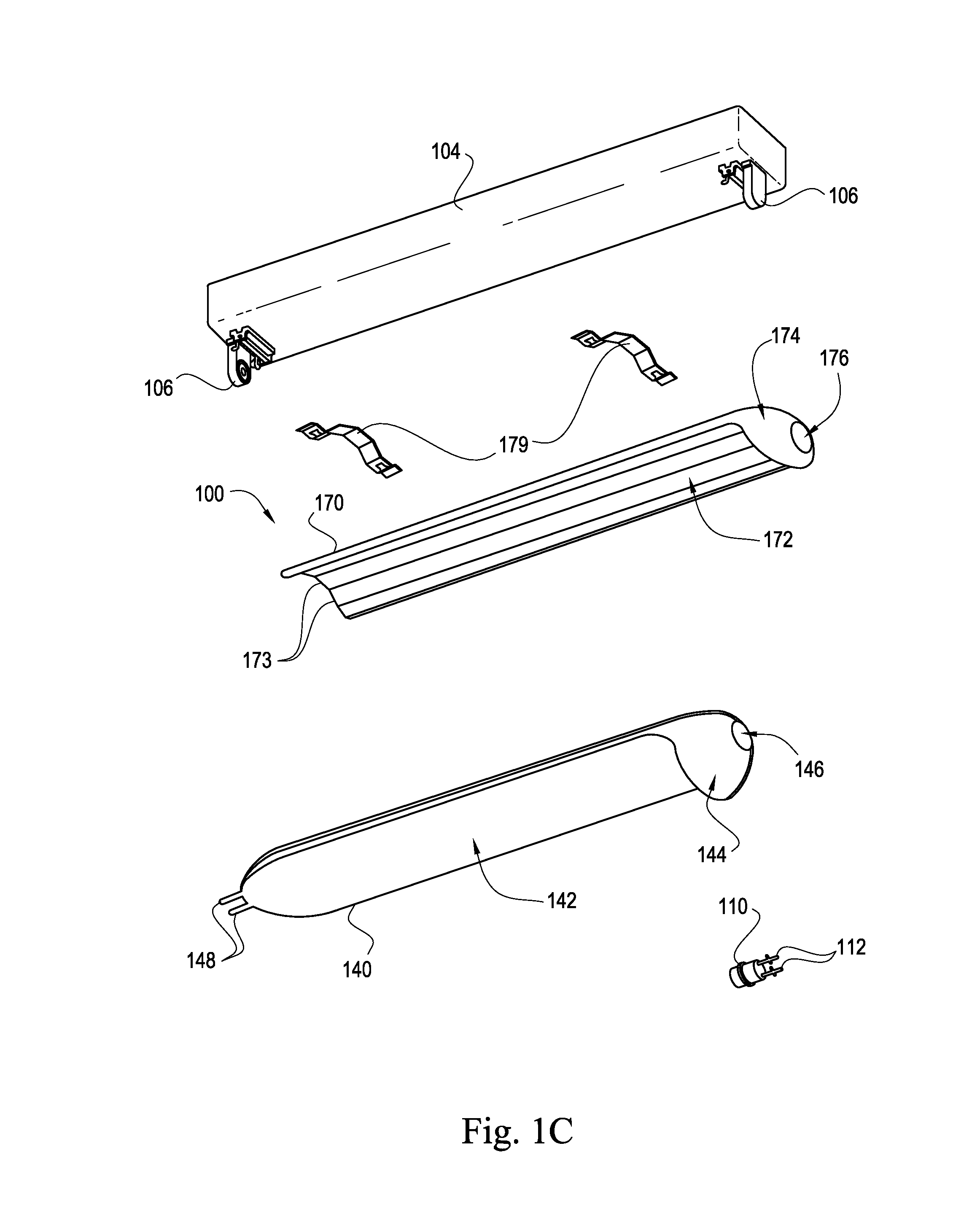
[0031]The present invention will now be described more fully hereinafter with reference to the accompanying drawings, in which preferred embodiments of the invention are shown. This invention may, however, be embodied in many different forms and should not be construed as limited to the embodiments set forth herein. Rather, these embodiments are provided so that this disclosure will be thorough and complete, and will fully convey the scope of the invention to those skilled in the art. Those of ordinary skill in the art realize that the following descriptions of the embodiments of the present invention are illustrative and are not intended to be limiting in any way. Other embodiments of the present invention will readily suggest themselves to such skilled persons having the benefit of this disclosure.

[0032]Although the following detailed description contains many specifics for the purposes of illustration, anyone of ordinary skill in the art will appreciate that many variations and a...


PUM

PropertyMeasurementUnit
color temperaturesaaaaaaaaaa
frequencyaaaaaaaaaa
voltageaaaaaaaaaa

Abstract

A fluorescent tube retrofit luminaire includes a lamp, a light guide, and a heat dissipating frame. The lamp may include a bi-pin base, middle structure, and outer structure, which may include a light-emitting diode (LED)-based light source in thermal communication with a finned heat sink section of the middle structure. Light emitted from the light source may be distributed generally along the length and / or width of the light guide. A bi-pin connector in the light guide may attach the luminaire to a first fluorescent socket. The bi-pin base may be received by a mounting aperture in the light guide before anchoring the luminaire to a second fluorescent socket using a pin-lock. The heat dissipating frame may be in thermal communication with both the light guide and the heat sink section of the lamp.

Description

RELATED APPLICATIONS[0001]This application claims the benefit under 35 U.S.C. §119(e) of U.S. Provisional Patent Application Ser. No. 61 / 709,325 filed on Oct. 3, 2012 and titled Elongated LED Lighting System and Associated Methods, the entire contents of which are incorporated herein by reference.FIELD OF THE INVENTION[0002]The present invention relates generally to the field of lighting and, in particular, to luminaires used to replace fluorescent lamps, and associated methods.BACKGROUND OF THE INVENTION[0003]A fluorescent lamp (also called a fluorescent tube) uses electrical current to excite a vapor within a glass tube resulting in the discharge of electrons. Visible light is produced when the electrons cause a material coating the inner wall of the glass tube to fluoresce. Linear fluorescent lamps are routinely used in commercial or institutional buildings, and are commonly installed in troffer light fixtures (recessed troughs installed in a ceiling) and pendant light fixtures (...

Claims


Application Information

Patent Timeline
Patent Type & Authority Patents(United States)
IPC IPC(8): F21V8/00F21K99/00F21V29/70
CPCF21K9/175F21K9/52F21V29/70F21K9/90Y02B20/386Y10T29/49117F21K9/27F21K9/60F21K9/61F21Y2115/10Y02B20/30F21V17/06
Inventor MAXIK, FREDRIC S.BARTINE, DAVID E.
Owner LIGHTING SCI GROUP
Why Eureka
Try Eureka