Ion mobility spectrometer and method of using the same

a technology of mobility spectrometer and ion, which is applied in the direction of instruments, particle separator tube details, separation processes, etc., can solve the problems of reducing the resolution of spectrum peaks and the resolution of a range of analytes, and achieve the effect of facilitating the prevention of the plurality of ions

Active Publication Date: 2015-09-29
RAPISCAN SYST INC (US)
View PDF28 Cites 19 Cited by
  • Summary
  • Abstract
  • Description
  • Claims
  • Application Information

AI Technical Summary

Benefits of technology

[0006]In one aspect, a method of detecting constituents in a sample is provided. The method includes channeling a sample gas stream to be tested for constituents into an ionization region and generating a plurality of ions in the ionization region. The method also includes substantially preventing the plurality of ions in the ionization region from flowing into a drift region coupled to the ionization region through inducing a first voltage in a device positioned between the ionization region and the drift region. The method further includes injecting at least a portion of the ions from the ionization region into the drift region including regulating the voltage in the device to a second voltage for a first predetermined temporal period. The second voltage is less than the first voltage. The method also includes regulating the voltage in the device to the first voltage and regulating the voltage in the device to the second voltage for a second predetermined temporal period. The second predetermined temporal period is different from the first predetermined temporal period.
[0007]In another aspect, an apparatus for detecting constituents in a sample is provided. The apparatus includes a casing, an ionization region at least partially defined by the casing, ...

Problems solved by technology

The higher mobility ions will also have higher spectrum peaks with longer gating pulses, but a significantly lower resolving power will result, thereby decreasing the resolution of the spectrum peaks.
As such, since known general purp...

Method used


Image

  • Ion mobility spectrometer and method of using the same
  • Ion mobility spectrometer and method of using the same
  • Ion mobility spectrometer and method of using the same

Examples


Embodiment Construction

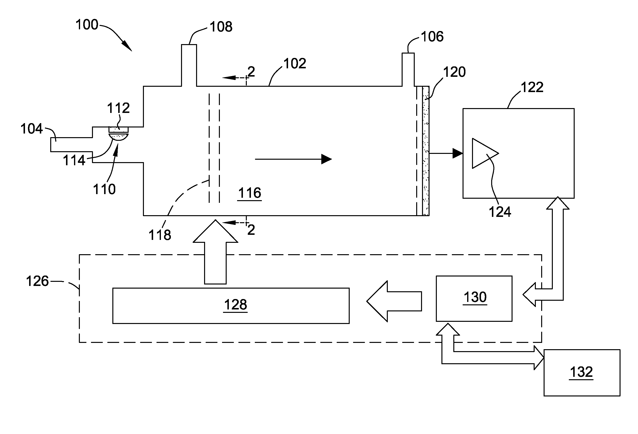
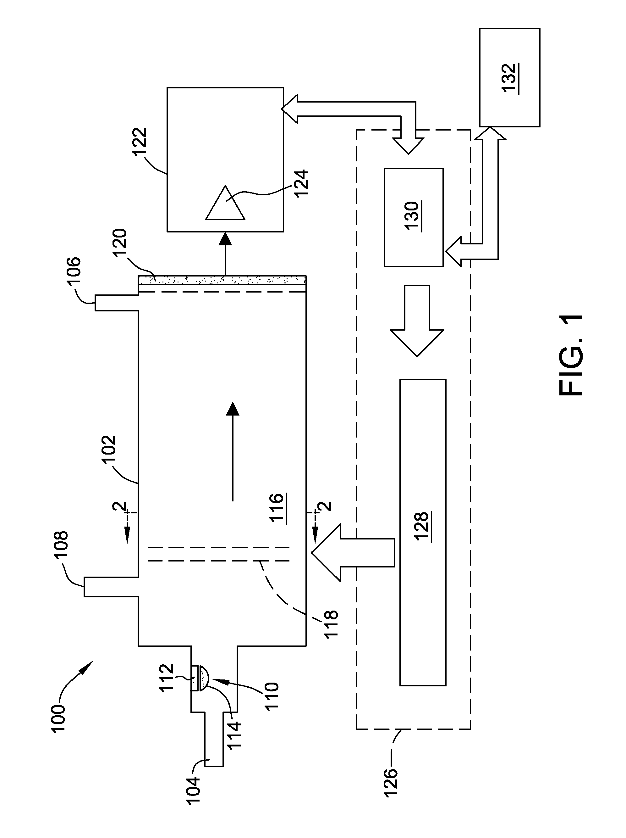
[0013]The embodiments described herein provide a cost-effective system and method for improving detection of materials of interest from an object or person. The systems and methods described herein use two different pulse widths to inject ions from an ionization region into a drift region during de-energization of an ion gate device. The first, i.e., narrower pulse width facilitates de-energizing the ion gate device for a shorter temporal period, thereby enhancing detection of high-mobility ions through generating a first spectral trace including a plurality of resolved high-mobility ion peaks. As such, resolution of spectral traces of high-mobility analytes is enhanced. The same first spectral trace includes a low-mobility ion peak having a first amplitude. The second, i.e., wider pulse width facilitates de-energizing the ion gate device for a longer temporal period, thereby enhancing detection of low-mobility ions through generating a spectral trace including a low-mobility ion pe...


PUM


Abstract

A method of detecting constituents in a sample includes generating a plurality of ions in an ionization region. The method also includes preventing the plurality of ions in the ionization region from flowing into a drift region through inducing a first voltage in a device positioned between the two regions. The method further includes injecting at least a portion of the ions from the ionization region into the drift region. The method also includes regulating the voltage in the device to a second voltage for a first predetermined temporal period, the second voltage less than the first voltage. The method further includes regulating the voltage in the device to the first voltage. The method also includes regulating the voltage in the device to the second voltage for a second predetermined temporal period, the second predetermined temporal period different from the first predetermined temporal period.

Description

BACKGROUND[0001]The embodiments described herein relate generally to an ion mobility spectrometer (IMS) and, more particularly, to an IMS detection system for enhancing detection of materials of interest through enhanced resolution of high-mobility ions and low-mobility ions.[0002]At least some known spectroscopic detection devices include a time-of-flight (TOF) ion mobility spectrometer (IMS) detection system. Such TOF-IMS detection systems are used to detect trace portions of materials of interest, e.g., residues, in the presence of interfering substances in collected samples. In at least some known TOF-IMS detection systems, ions are generated in an ionization region to increase the ion population therein. An ion gate (sometimes referred to as an ion shutter) that includes a conducting grid of interleaved wires, e.g., a Bradbury-Nielson gate, is maintained in a “cut-off” condition that is configured to prevent an ion current to transmit from the ionization region. Energizing the ...

Claims


Application Information

Patent Timeline
IPC IPC(8): B01D59/44H01J49/02G01N27/62H01J49/40H01J49/00H01J49/28
CPCH01J49/022G01N27/622H01J49/06
Inventor GOEDECKE, LYNDON KARL
Owner RAPISCAN SYST INC (US)
Why Eureka
Try Eureka