Radiant heating umbrella

Active Publication Date: 2015-10-06
DAVIS MARVIN ROBERT
View PDF10 Cites 3 Cited by
  • Summary
  • Abstract
  • Description
  • Claims
  • Application Information

AI Technical Summary

Benefits of technology

[0010]In one embodiment of the invention an apparatus is provided, comprising a fuel-burning radiant heater radiating heat outwardly from the infra-red heat source, an upwardly convex reflector having an outside reflector diameter substantially greater than the outside perimeter of the radiant heater, the reflector having inner surfaces oriented to reflect radiant heat from the heater downward below the heater, the surfaces converging to an upper central opening, the reflector joined to the radiant heater with the center opening aligned with and spaced above the heater, a vertically-oriented cylindrical ring shield joined to the bottom of the reflector at the outside reflector diameter, the ring shield having a dimension extending downward to block radiant heat from passing horizontally beyond the outside reflector diameter, thus shielding a canopy from direct radiant heat, an upwardly convex metal hood having a hood diameter greater than the outside reflector diameter, and a hood opening concentric with and greater in diameter than the upper central opening of the reflector, t

Problems solved by technology

Such heaters are large and cumbersome and may present as obstacles for patrons when placed in numbers to heat a general area, and can conflict with umbrellas in the same area.
A major drawback of this configuration is that the distance the gas must travel before cooling to a safe temperature is several times greater than for an unmodified patio heater.
While the heated umbrella better utilizes available patio space than does a large cumbersome floor heater, there are several additional problems w

Method used


Image

  • Radiant heating umbrella
  • Radiant heating umbrella
  • Radiant heating umbrella

Examples


Embodiment Construction

[0018]In various embodiments described in enabling detail herein, the inventor provides a radiant heating umbrella that solves the problems of the prior art. The present invention is described using the following examples, which may describe more than one relevant embodiment falling within the scope of the invention.

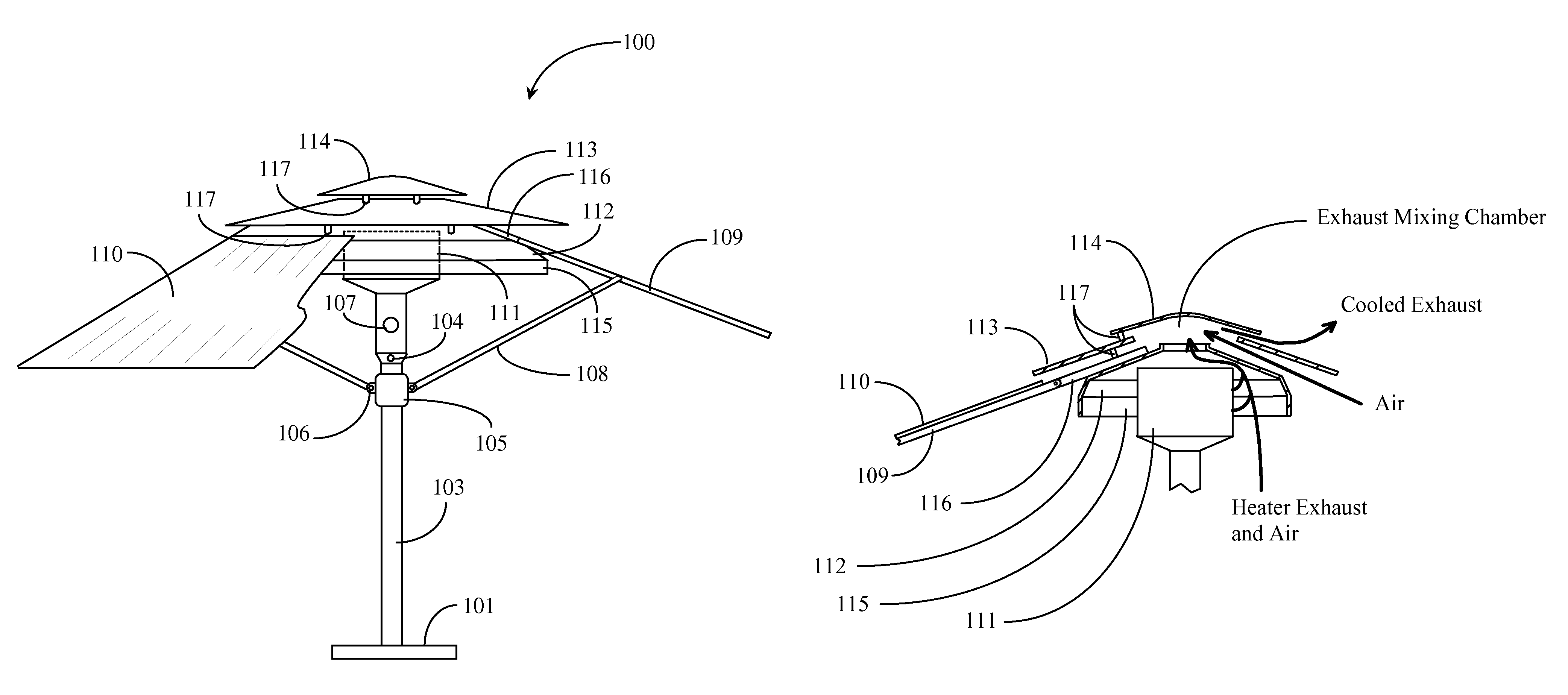
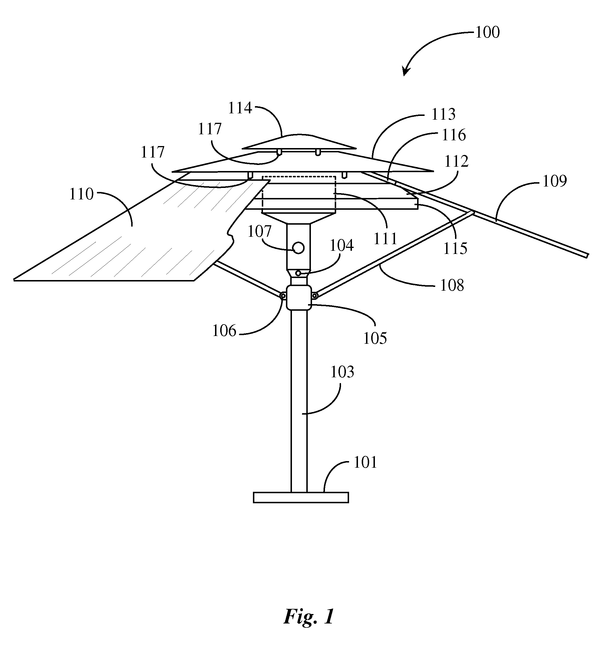
[0019]FIG. 1 is an elevation view of a radiant heater unit 100 according to an embodiment of the present invention. Heater unit 100 is in the form of a patio umbrella that has been manufactured or otherwise modified to incorporate a heater core 111 as a source of radiant heat available through operation of the umbrella. Radiant heater unit 100 may be referred to in this specification as umbrella 100.

[0020]Umbrella 100 has a base portion 101. Base portion 101 includes a platform and upright tubular or otherwise hollow body 103 manufactured of a resilient and durable material such as steel, aluminum, high grade polymer or other resilient materials. In one embodiment, base ...


PUM


Abstract

An apparatus having a radiant heater, an upwardly convex reflector, a vertically-oriented cylindrical ring shield joined to the reflector at the outside reflector diameter, an upwardly convex metal hood, and an upwardly convex cap having a cap diameter greater than the diameter of a hood opening, wherein exhaust gases emitted upwardly from the exhaust port draw cooler air through the cylindrical opening, the exhaust gases and cooler air pass upward through the hood, drawing additional cooler air through the annular space between the reflector and the hood, into a mixing chamber formed by the cap and the hood, where the cooler air and the exhaust gases mix and the mixed air and exhaust gases then pass outward through the annular space between the cap and the hood, exiting the apparatus at the outer diameter of the cap.

Description

BACKGROUND OF THE INVENTION[0001]1. Field of the Invention[0002]The present invention is in the field of heating apparatus for human comfort and pertains more particularly to methods and apparatus for heating in the vicinity of a patio umbrella and host dining or patio table.[0003]2. Discussion of the State of the Art[0004]There are a wide variety of outdoor heating apparatus that are available for space heating in outdoor or otherwise un-heated settings. A typical fuel-burning radiant heater may be placed in an outdoor dining area, for example to provide radiant heat for patrons sitting within the influence sphere of the heater. Some businesses such as restaurants with an outdoor patio area have provided such heaters placed strategically throughout the patio dining area to provide such heating of the area.[0005]A typical radiant heater currently available burns natural gas or propane. The heater operates at temperatures at which infrared radiant heat is produced. An annular or quas...

Claims


Application Information

Patent Timeline
IPC IPC(8): A45B23/00F24C1/12
CPCA45B23/00F24C1/12A45B2200/1009A45B2023/0012A45B2025/186
Inventor DAVIS, MARVIN ROBERT
Owner DAVIS MARVIN ROBERT
Why Eureka
Try Eureka