Systems and methods for improved direct drive generators

a direct drive generator and direct drive technology, applied in the direction of mechanical energy handling, magnetic circuit rotating parts, magnetic circuit shape/form/construction, etc., can solve the problems of direct drive generator weight, common bearing system stiffness, and weight of direct drive generator, so as to reduce the weight and size of transportable components, and alleviate the disadvantage of magnetic attractive forces

Inactive Publication Date: 2015-10-06
BWP GRP
View PDF299 Cites 53 Cited by
  • Summary
  • Abstract
  • Description
  • Claims
  • Application Information

AI Technical Summary

Benefits of technology

[0015]The present invention can provide a system and method for reducing the weight and size of transportable components of a direct drive generator. In an exemplary embodiment, a direct drive or directly driven axial flux generator is provided, the generator comprising a stator having at least one stator element for power generation and a rotor rotatable around a center axis of the generator having at least one rotor element for power generation; the generator having an axial air gap between the stator element and rotor element, wherein the at least one stator element and the at least one rotor element are located at substantially the same radial distance from the center axis so as to allow for electrical generation during their relative motion. The generator may further comprise arc-shaped axially connectable stator supports, the stator elements being axially and circumferentially attached to the arc-shaped supports of the stator, wherein junctions between the arc-shaped supports of the stator and stator elements are located substantially at a position on the circumference of a radius which is substantially larger than the center axis of the generator; with the complete assembled generator having the appearance of a disc-shaped ring having a very large, somewhat open center with a spoked or other similar connecting structure.
[0028]In another exemplary embodiment, the present invention incorporates a sectioned easily shippable support structure to which a number of detachable, multi-layered, printed circuit board stator segments and an associated set of detachable rotor sections. Preferably, the rotor sections, to which permanent magnets are affixed, are axially positioned on each side of the stator elements (in this case, multi-layered, printed circuit board stator segments) at a specified axial gap, which is maintained by a gap control means during operation after the generator is assembled and installed into the turbine. The shippable support structure and associated stator and rotor components are designed to be easily assembled on the site of turbine erection to form a complete operating generator. One embodiment of the generator is approximately eight meters in diameter as a complete assembly, but is transported in quadrants that are no greater than four meters in the vertical dimension, thus allowing transportability.

Problems solved by technology

While the large outer diameter has advantages, it also causes numerous issues for direct drive generators.
Among other problems, the large outer diameter causes problems with transporting, lifting, assembling, repairing, and replacing the direct drive generator.
These problems are due not only to the size of the device (which significantly impacts transport) but also the weight of the direct drive generator.
In addition, the support structure, commonly a bearing system is also very stiff.
Additionally, the heavy weight of a multi-megawatt generator of conventional design necessitates additional infrastructure support in the turbine tower and related components, which adds cost and complexity.
However, this construction requires a stator housing having relatively large outer dimensions.
The drawbacks of this configuration are that the electromechanical properties in this form of modular construction, with single polar pairs separated by air gaps, may be disadvantageous; that a possible dismantling of a single stator module can require that the whole generator has to be opened in situ thus implying risk of humidity, dirt, etc.
; and that it may be cumbersome if the stator module has to be taken out in a disadvantageous direction.
But even if no part is larger than the air gap diameter, the largest element to be transported still has a substantial size, given that the rotor is a single piece.
Although present devices are functional, they are not sufficiently efficient, effective or otherwise satisfactory.

Method used


Image

  • Systems and methods for improved direct drive generators
  • Systems and methods for improved direct drive generators
  • Systems and methods for improved direct drive generators

Examples


Embodiment Construction

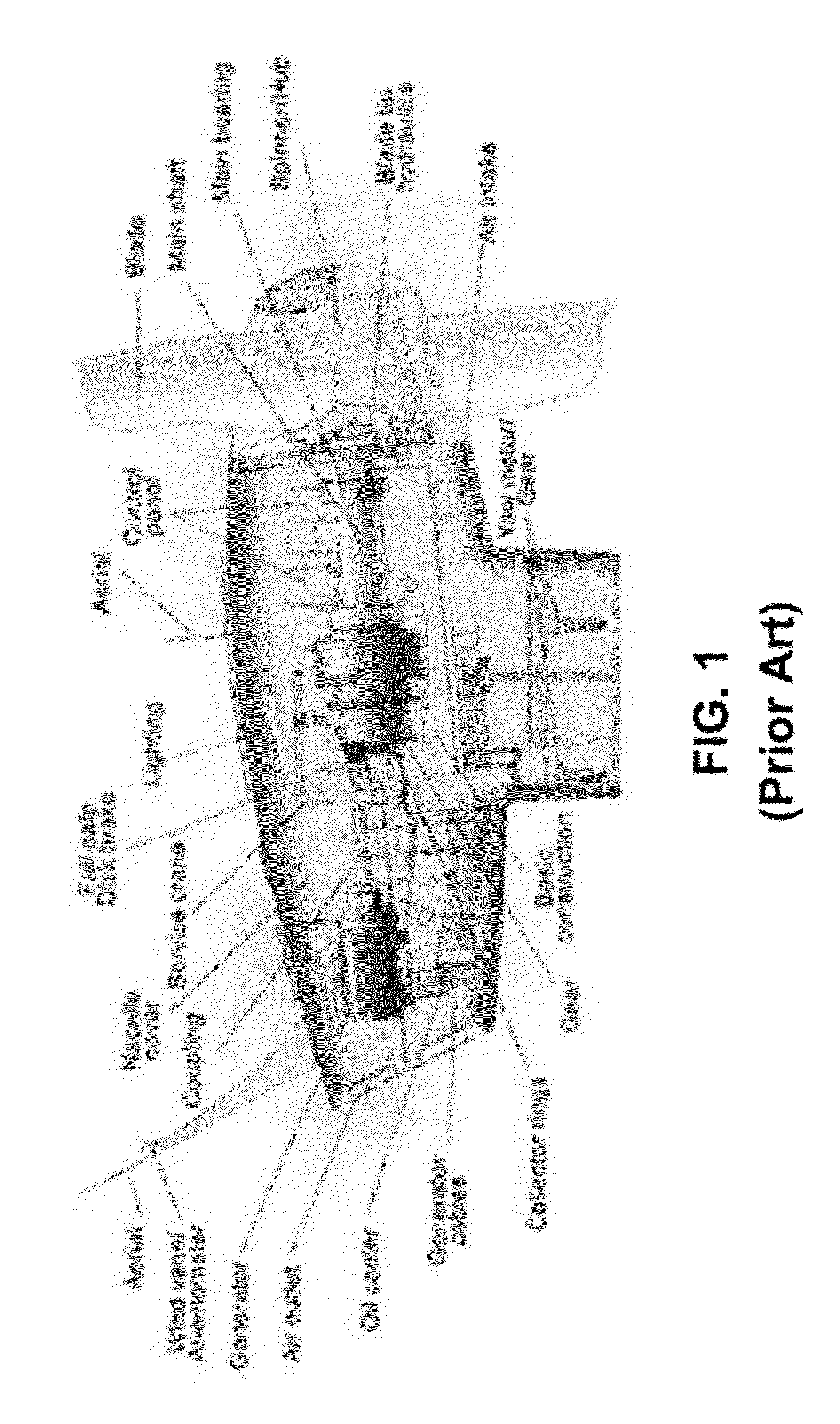
[0066]In the following detailed description, and in the attached drawings, the present invention is described relative to a wind turbine. This is for description only and is not intended to limit the scope or use of the present invention. The present invention provides a generator, and components thereof, wherein the transport of the generator, the construction of the generator, and / or the repair of the generator is simplified. While it is a further object of the invention to incorporate the described generator into a wind turbine, the present invention is not limited to wind turbines.

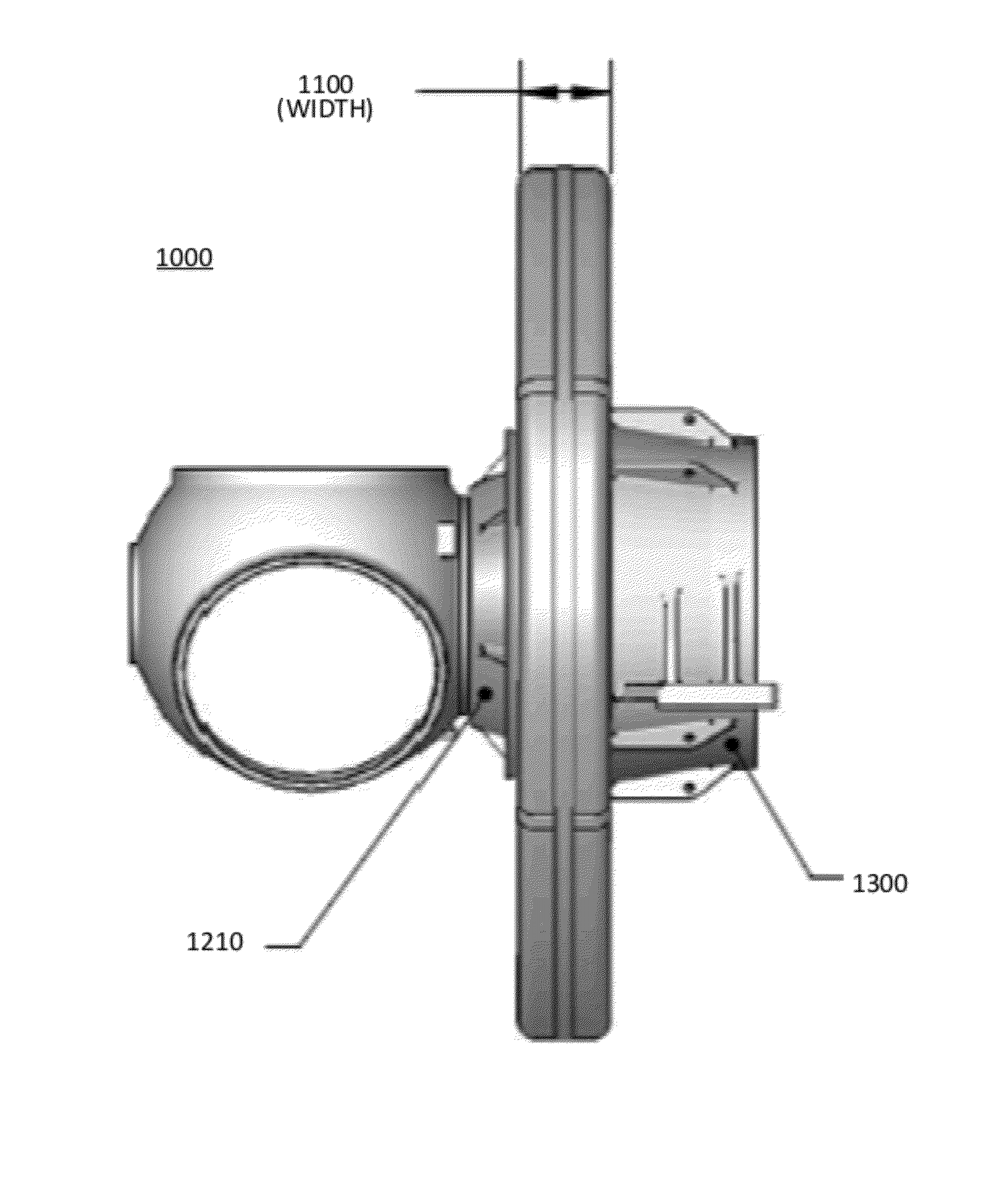
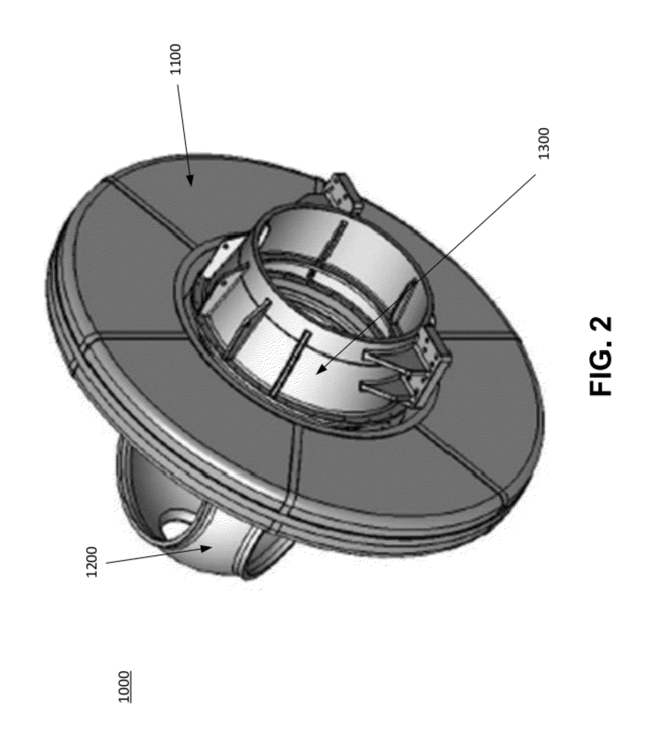
[0067]Referring first to FIGS. 2-8, depicted are various external views of a direct drive generator 1000 consistent with an embodiment of the present invention. A generator (housing) 1100 is shown attached to a hub 1200, wherein the hub 1200 is configured to hold blades for a wind turbine. The hub 1200 attaches to the generator (housing) 1100 by a rotor hub casting 1210. On the other side, the generato...


PUM


Abstract

Systems and methods for improved generators are described. One embodiment includes an assembly for an axial flux generator, the assembly comprising an arc-shaped rotor section that includes a rotor support configured to rotate around an axis of a generator, and an at least one rotor element for power generation that is connected to the rotor support; an arc-shaped stator section comprising a stator support and an at least one stator element for power generation connected to the stator support; wherein the rotor section and the stator section are configured to provide an axial air gap between the at least one rotor element and the at least one stator element, and wherein the at least one rotor element and the at least one stator element are positioned to be at substantially the same radial distance from the axis of the generator.

Description

PRIORITY[0001]The present application claims priority to commonly owned and assigned provisional application No. 61 / 350,850, filed Jun. 2, 2010, entitled “Systems and Methods for Improved Direct Drive Generators,” and provisional application No. 61 / 517,040, filed Apr. 12, 2011, entitled “Air Gap Control System,” both of which are incorporated herein by reference.RELATED APPLICATIONS[0002]The present application is related to commonly owned and assigned application no. PCT / US2010 / 000112, entitled “Segmented Stator for an Axial Field Device,” which is incorporated herein by reference.FIELD OF THE INVENTION[0003]The present invention relates to electrical generation devices, including stator / rotor design and assembly, and systems and methods for support structure. The field of the invention includes the design, manufacturing and operation of rotating electromagnetic machines—typically called electric motors or electric power generators.BACKGROUND OF THE INVENTION[0004]In principle ther...

Claims


Application Information

Patent Timeline
Patent Type & Authority Patents(United States)
IPC IPC(8): H02K21/24H02K7/18H02K1/30
CPCH02K21/24H02K1/30H02K7/1838H02K2201/15Y02E10/725H02K16/04Y02E10/72
Inventor JORE, MATTHEW B.JORE, LINCOLNKVAM, MICHAEL A.JORE, JAMES D.SAMSEL, DAVIDDUFORD, JAMES DAVIDSMITH, JAMES S.
Owner BWP GRP
Why Eureka
Try Eureka