Time encoded circuits and methods and a time encoder based beamformer for use in receiving and transmitting applications

a time encoded circuit and beamformer technology, applied in the field of chipscale analog beam forming engine, can solve the problems of large number of long and precisely cut optical cables, large physical and lossy devices, and wide bandwidth operation

Active Publication Date: 2015-10-06
HRL LAB
View PDF47 Cites 15 Cited by
  • Summary
  • Abstract
  • Description
  • Claims
  • Application Information

AI Technical Summary

Benefits of technology

[0012]In one aspect the present invention provides a method of delaying a pulse domain signal comprising: applying an inputted pulse domain signal to a time encoder circuit; and controlling an amount o...

Problems solved by technology

Passive or active phase shifters are inherently narrowband devices that cannot be used for wide bandwidth operation.
Also, they are physically large and lossy devices.
The RF-to-optical and optical-to-RF transformations are typically lossy processes that require power hungry optical modulator and demodulator devices.
Also, a large number of long and precisely cut optical cables are required to obtain fine granulites in the beam angle resolution.
While the photonics beam forming b...

Method used


Image

  • Time encoded circuits and methods and a time encoder based beamformer for use in receiving and transmitting applications
  • Time encoded circuits and methods and a time encoder based beamformer for use in receiving and transmitting applications
  • Time encoded circuits and methods and a time encoder based beamformer for use in receiving and transmitting applications

Examples


Embodiment Construction

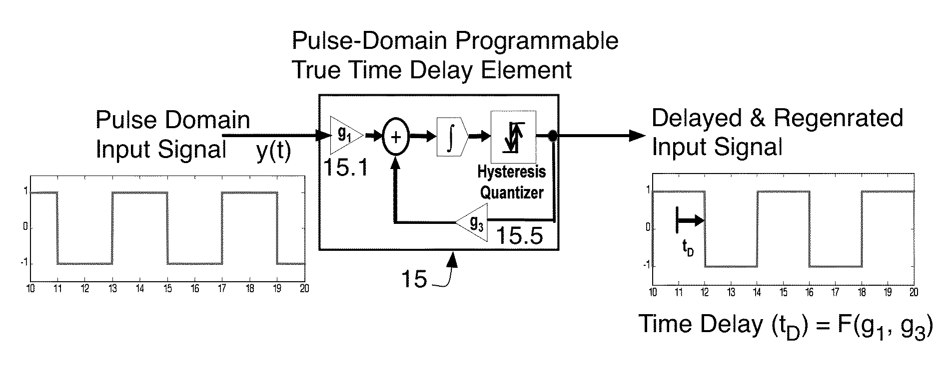
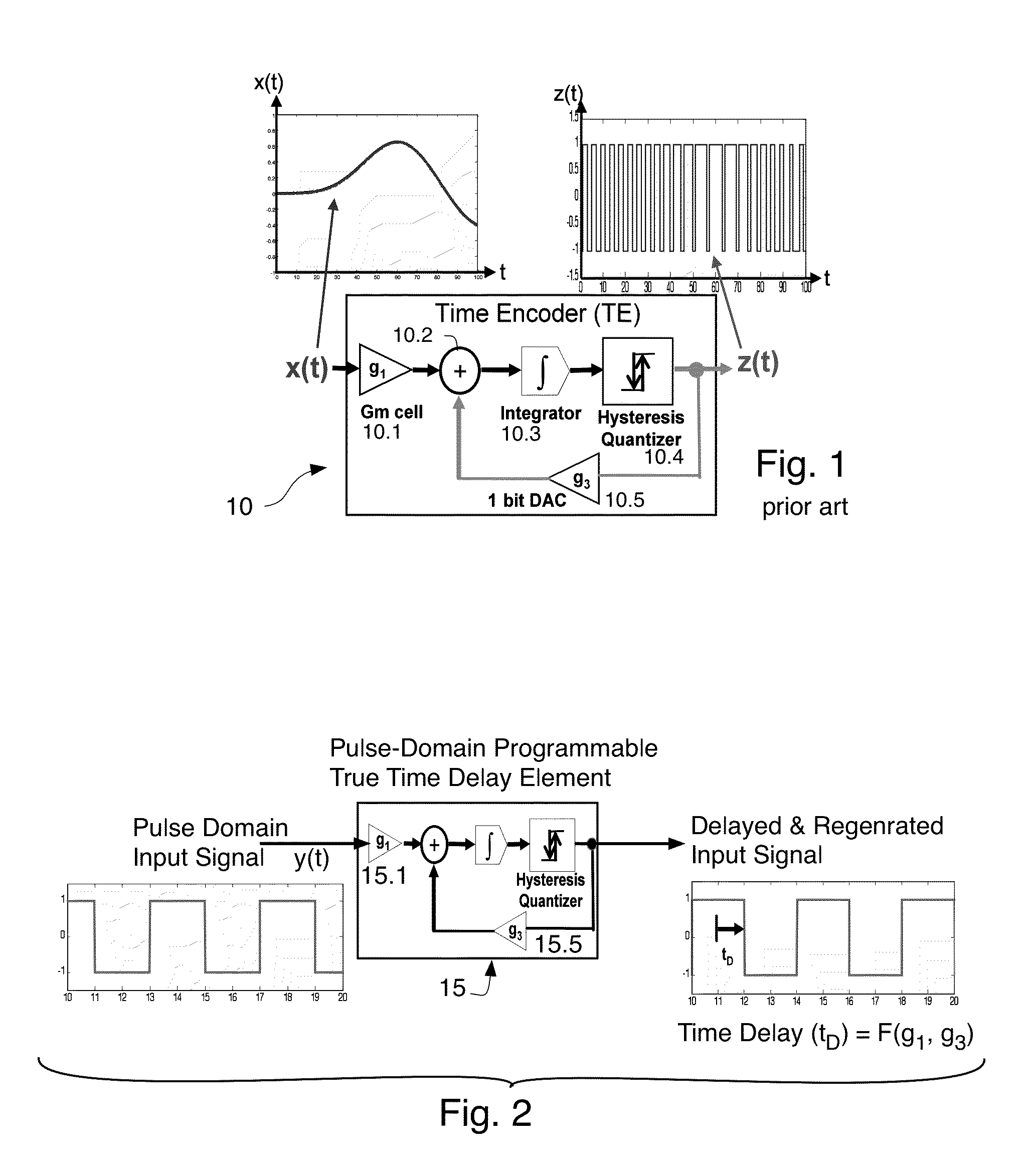
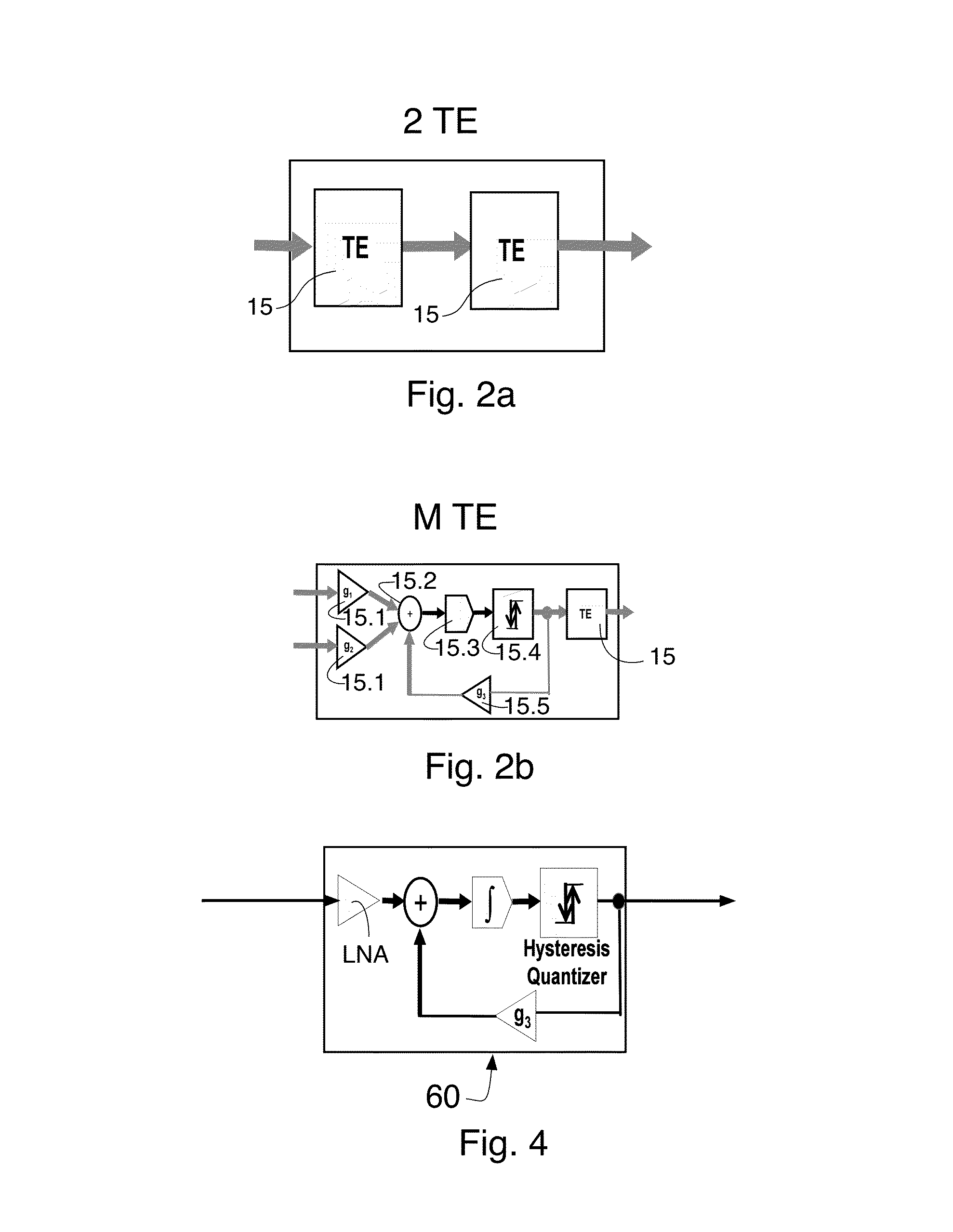
[0027]This invention utilizes arrays of time encoders to form both receive and transmit beamformers. A prior art embodiment of a time encoder 10 is now described with reference to FIG. 1. This time encoder is known per se in the prior art. It is modified (see FIG. 2 where the reference number 15 refers to a modified version thereof used in arrays (described below)). In the prior art device of FIG. 1 a continuous-amplitude and continuous-time analog signal x(t) is transformed into the Asynchronous Pulse Domain (APD) using a process called “time encoding.” The time-encoding process converts the continuous amplitude and continuous time analog signal x(t) into an asynchronous pulse sequence z(t) as shown in FIG. 1. Preferably, no information is lost in this process and preferably no quantization noise is introduced during the time-encoding process. It has recently been proven (see Lazar, A. A. and Toth, L. T. “Perfect recovery and sensitivity analysis of time encoded bandlimited signals...


PUM


Abstract

A method delaying a pulse domain signal using a time encoder circuit and a time encoder based beamformer method and apparatus for use in receiving and/or transmitting applications.

Description

CROSS REFERENCE TO RELATED PATENTS[0001]This application is related to the technology disclosed in U.S. Pat. No. 7,515,084, the disclosure of which is hereby incorporated herein by reference.STATEMENT REGARDING FEDERAL FUNDING[0002]None.TECHNICAL FIELD[0003]The invention relates to chip-scale analog beam forming engine for receive and / or transmit Active Electronically Scanned Array (AESA) applications.BACKGROUND[0004]This invention relates to a novel chip-scale analog beam forming engine for receive array applications consisting of IC chips. The beam forming engine is based upon HRL's Asynchronous Pulse Processor (APP) circuit technology disclosed in U.S. Pat. No. 7,592,939 entitled “Digital domain to pulse domain time encoder” the disclosure of which is hereby incorporated herein by reference. APP involves using Pulse domain processing with time encoders. Pulse processing for other applications is described in other issued US patents assigned to the assignee of the present applicat...

Claims


Application Information

Patent Timeline
IPC IPC(8): H04B1/18H03K3/86
CPCH04B1/18H03K3/86H04B7/0617H04B7/0671H01Q3/26H01Q3/2682H03K19/0016H03K19/00369
Inventor CRUZ-ALBRECHT, JOSEPETRE, PETERJENSEN, JOSEPH F.
Owner HRL LAB
Why Eureka
Try Eureka