Unlock instant, AI-driven research and patent intelligence for your innovation.

Underground cavity detection by electromagnetic shock waves

a technology of electromagnetic shock waves and underground cavity, which is applied in the direction of geological measurements, electric/magnetic detection for welllogging, using reradiation, etc., can solve the problems of limited penetration ability in a ground with high conductivity, low resolution, and sensitive methods, so as to improve reliability and survivability, the effect of improving directionality

Active Publication Date: 2015-10-13
STATE OF ISRAEL - SOREQ NUCLEAR RES CENT
View PDF5 Cites 4 Cited by
  • Summary
  • Abstract
  • Description
  • Claims
  • Application Information

AI Technical Summary

Benefits of technology

This patent describes a method for identifying underground structures using a distributed long line antenna. The method has advantages over conventional borehole tomography, including the ability to save time by localizing based on signal arrival time, and better directionality resulting from conical wave propagation. Compared to methods involving underground components, the present invention uses simpler passive hardware and requires smaller borehole diameters for increased reliability and survivability.

Problems solved by technology

This method, however, is sensitive to ferromagnetic bodies only.
This method, however, has limited penetration ability in a ground with high conductivity.
However, low frequencies result in low resolution.
This method has the same disadvantage of penetration vs. resolution.
This scan is typically done mechanically and takes a long time to complete.

Method used


Image

  • Underground cavity detection by electromagnetic shock waves
  • Underground cavity detection by electromagnetic shock waves
  • Underground cavity detection by electromagnetic shock waves

Examples


Embodiment Construction

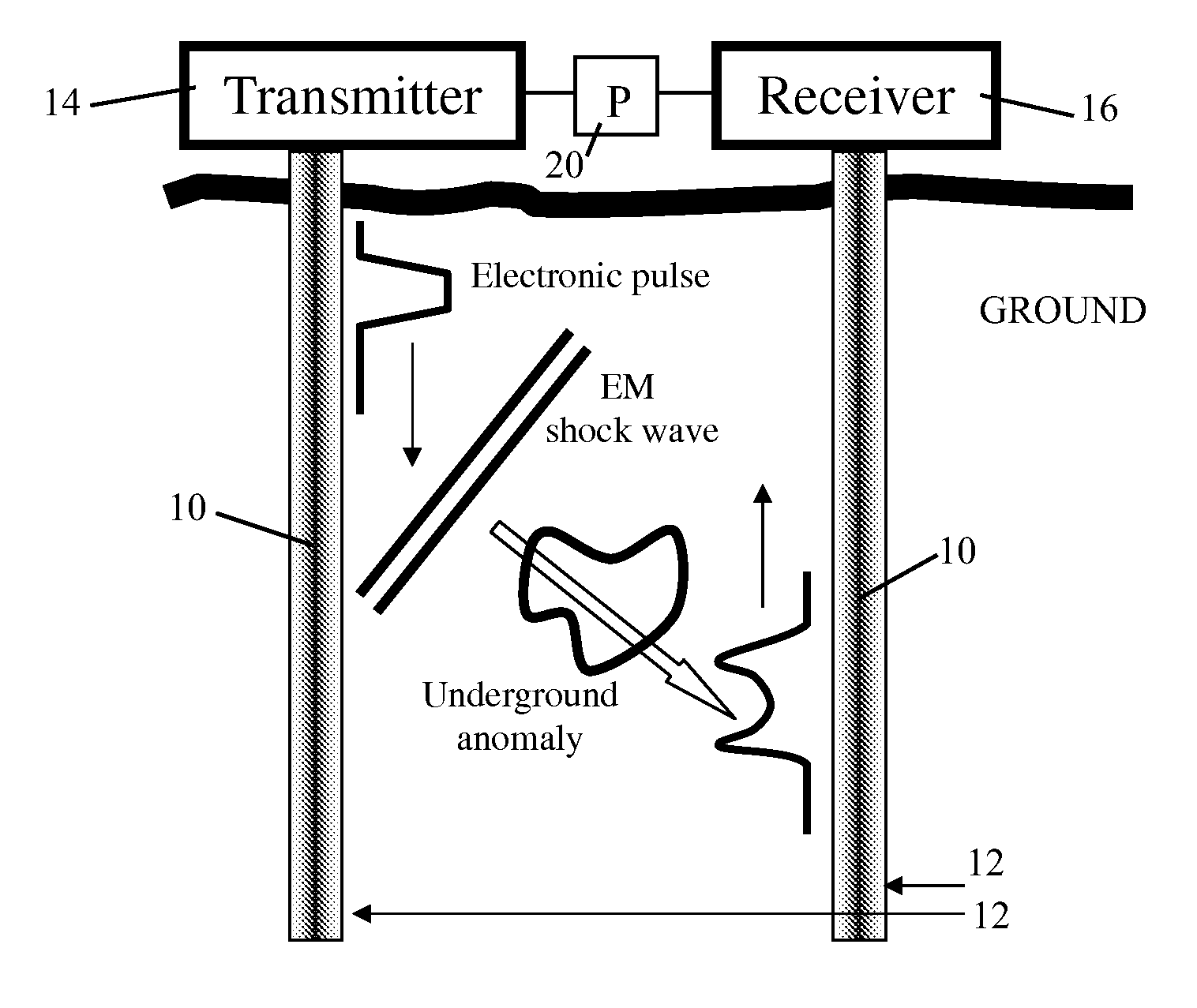
[0027]Reference is now made to FIG. 1, which illustrates a system for detection of underground anomalies underneath or in the ground, including two boreholes extending to a depth into the ground, in accordance with an embodiment of the present invention. The invention shortens the time-consuming procedure of localizing underground anomalies by the borehole tomography method.

[0028]A distributed antenna 10 (also called a leaky transmission line 10) is inserted into each borehole 12. A transmitter 14 is connected to one of the distributed antennas 10 and a receiver 16 is connected to the other distributed antenna 10. The transmitter 14 generates an electronic pulse that propagates through the line (antenna 10). The signal leaks outside of antenna 10 while propagating. The line is chosen with dielectric and magnetic constants smaller than those of the ground and therefore the speed of electromagnetic wave propagation through the line is faster than the speed of propagation through the g...


PUM


Abstract

A method for detection of underground anomalies including in a system of distributed antennas (10), which are leaky transmission lines, disposed in 16 boreholes (12) formed in a ground, a transmitter (14) being connected to one of the antennas (10), and a receiver (16) being connected to another of the antennas (10), injecting an electromagnetic pulse into one of the antennas (10), wherein the pulse gradually leaks out, and wherein if a speed of propagation in the line in which the pulse is injected is faster than a speed of propagation in the ground, a shock wave is transmitted through the ground, called a transmitted signal, and received as a received signal at another of the antennas (10), and wherein an underground anomaly diffracts the shock wave, resulting in a detectable disturbance in the received signal, and locating the anomaly as a function of a time delay of the disturbance relative to the transmitted signal.

Description

CROSS-REFERENCE TO RELATED APPLICATIONS[0001]This application is a national phase application of PCT patent application PCT / US11 / 020072, filed 4 Jan. 2011, which claims priority under 35 USC §119 to U.S. Provisional Patent Application Ser. No. 61 / 291,973, filed 4 Jan. 2010, which are incorporated herein by reference.FIELD OF THE INVENTION[0002]This invention relates generally to detection by electromagnetic (EM) waves of an underground anomaly such as a cavity, pipe, or any material bulk which differs from its surround by its EM properties. More particularly, the invention relates to underground detection by EM waves transmitted and received via boreholes.BACKGROUND OF THE INVENTION[0003]Detection and ranging of underground anomalies is important for a variety of applications, such as detecting underground cavities, unmapped infrastructure pipelines, and ores. The magnetic method measures anomalies with respect to the earth magnetic field. This method, however, is sensitive to ferro...

Claims


Application Information

Patent Timeline
Patent Type & Authority Patents(United States)
IPC IPC(8): G01V3/30G01S13/88G01S13/04
CPCG01V3/30G01S13/88G01S13/04
Inventor KESAR, AMITGINZBURG, BORIS
Owner STATE OF ISRAEL - SOREQ NUCLEAR RES CENT