Millimeter waveband filter and method of manufacturing the same

a filter and millimeter waveband technology, applied in the field of filters, can solve the problems of difficult manufacturing at a frequency over 100 ghz, difficulty in strict measurement of unnecessary emission or the like, and inability to separate harmonics, etc., to achieve accurate positioning, accurate positioning of three transmission lines, and high selection characteristics

Active Publication Date: 2015-10-13
ANRITSU CORP
View PDF3 Cites 0 Cited by
  • Summary
  • Abstract
  • Description
  • Claims
  • Application Information

AI Technical Summary

Benefits of technology

[0050]As described above, the millimeter waveband filter of the invention has the following structure. In the first waveguide, one of the pair of electric wave half mirrors is fixed to the transmission line, and in the second waveguide, the first transmission line which receives one end of the first waveguide at the gap from the outer circumference of the first waveguide and the second transmission line which has the same size as the transmission line of the first waveguide and to which the other electric wave half mirror is fixed are arranged concentrically and successively. The second waveguide is relatively moved with respect to the first waveguide such that the interval between the pair of electric wave half mirrors is changed, and the electromagnetic wave at the resonance frequency to be determined by the interval between the electric wave half mirrors is selectively transmitted. The second waveguide has a structure in which the first transmission line forming body has the square hole forming the first transmission line in the plate-shaped portion having a uniform thickness to pass through the plate-shaped portion in the thickness direction, the second transmission line forming body has the square hole forming the second transmission line in the plate-shaped portion having a uniform thickness to pass through the plate-shaped portion in the thickness direction, and the first transmission line forming body and the second transmission line forming body are connectable and separable in a state where the plate-shaped portions overlap each other such that the square holes are arranged concentrically and successively.
[0051]In this way, a resonator having a pair of flat electric wave half mirrors is provided inside the successive transmission lines which transmit only the TE10 mode. For this reason, a special device for inputting plane waves is not required, and the electric wave half mirrors do not need to transmit plane waves and may have an arbitrary shape.
[0052]The filter is of a closed type as a whole, and there is no loss by emission to the external space in principle, whereby very high selection characteristics can be realized in the millimeter waveband.
[0053]The second waveguide is formed such that the first transmission line forming body and the second transmission line forming body are connectable and separable in a state where the plate-shaped portions overlap each other. For this reason, it is possible to observe the gap between the outer circumference of the first waveguide and the square hole forming the first transmission line from the first transmission line forming body side, and to accurately perform the positioning. After the positioning, if the second transmission line forming body is connected to the first transmission line forming body such that the plate-shaped portions overlap each other at the positions positioned in advance, the second transmission line is not inclined with respect to the first transmission line, and it is possible to accurately perform the positioning of the three transmission lines and to maintain high filter characteristics.
[0054]In a structure in which the first transmission line forming body and the choke forming body overlap each other, and a groove for electromagnetic wave leakage prevention is formed, it is possible to suppress leakage of electromagnetic waves from the gap between the outer circumference of the first waveguide and the inner circumference of the first transmission line of the second waveguide, thereby preventing degradation in filter characteristics by the gap.
[0055]In a structure in which the air duct is provided, it is possible to prevent distortion of the electric wave half mirror by air pressure at the time of frequency variation, thereby stably performing frequency variation.

Problems solved by technology

In the conventional measurement technologies, it is not possible to separate harmonics of local oscillation from the measurement result, and there is difficulty in strict measurement of unnecessary emission or the like.
Meanwhile, manufacturing is difficult at a frequency over 100 GHz.

Method used


Image

  • Millimeter waveband filter and method of manufacturing the same
  • Millimeter waveband filter and method of manufacturing the same
  • Millimeter waveband filter and method of manufacturing the same

Examples


Embodiment Construction

[0068]Hereinafter, an embodiment of the invention will be described.

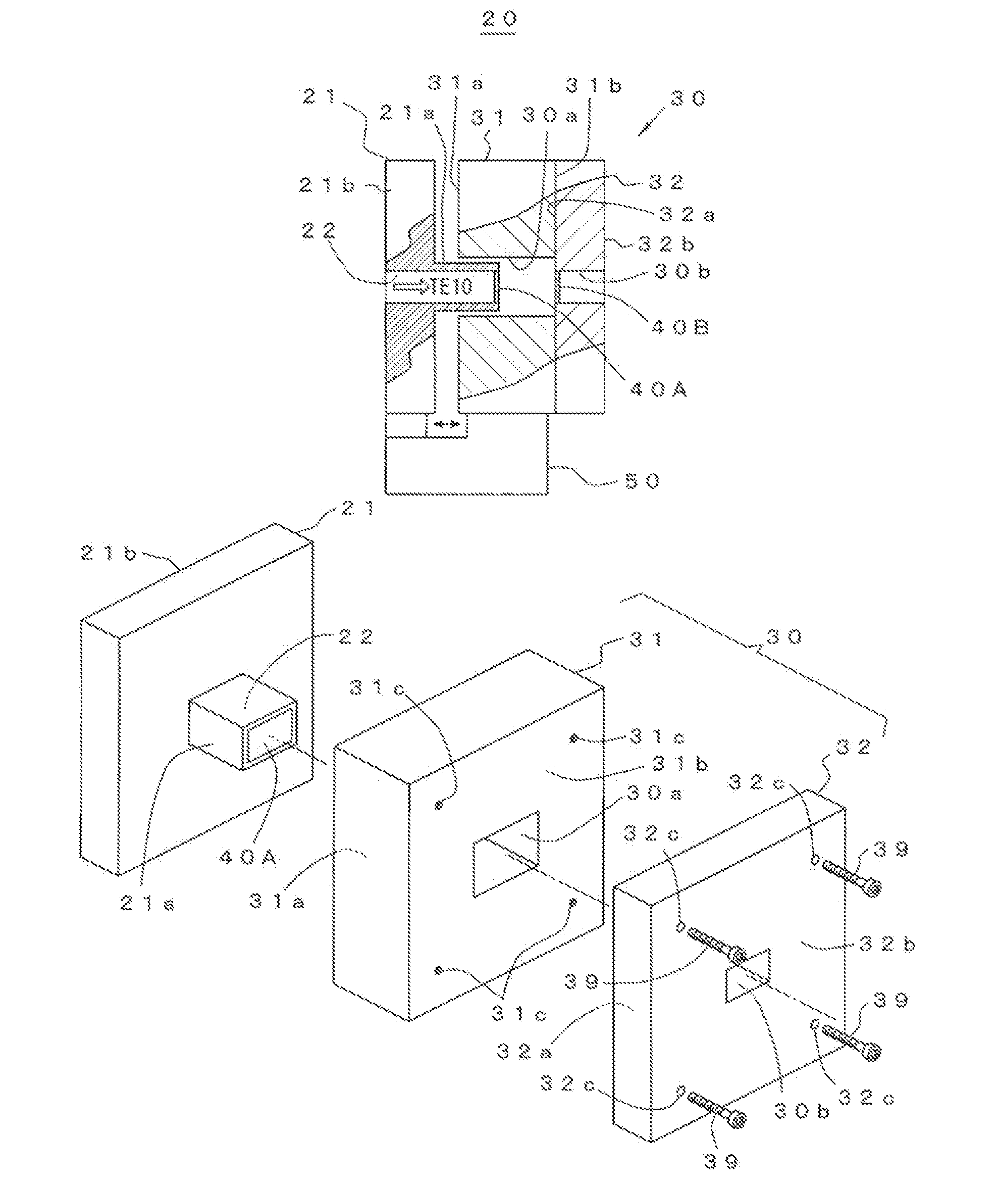
[0069]FIGS. 1A and 1B show the basic structure of a millimeter waveband filter 20 of the invention.

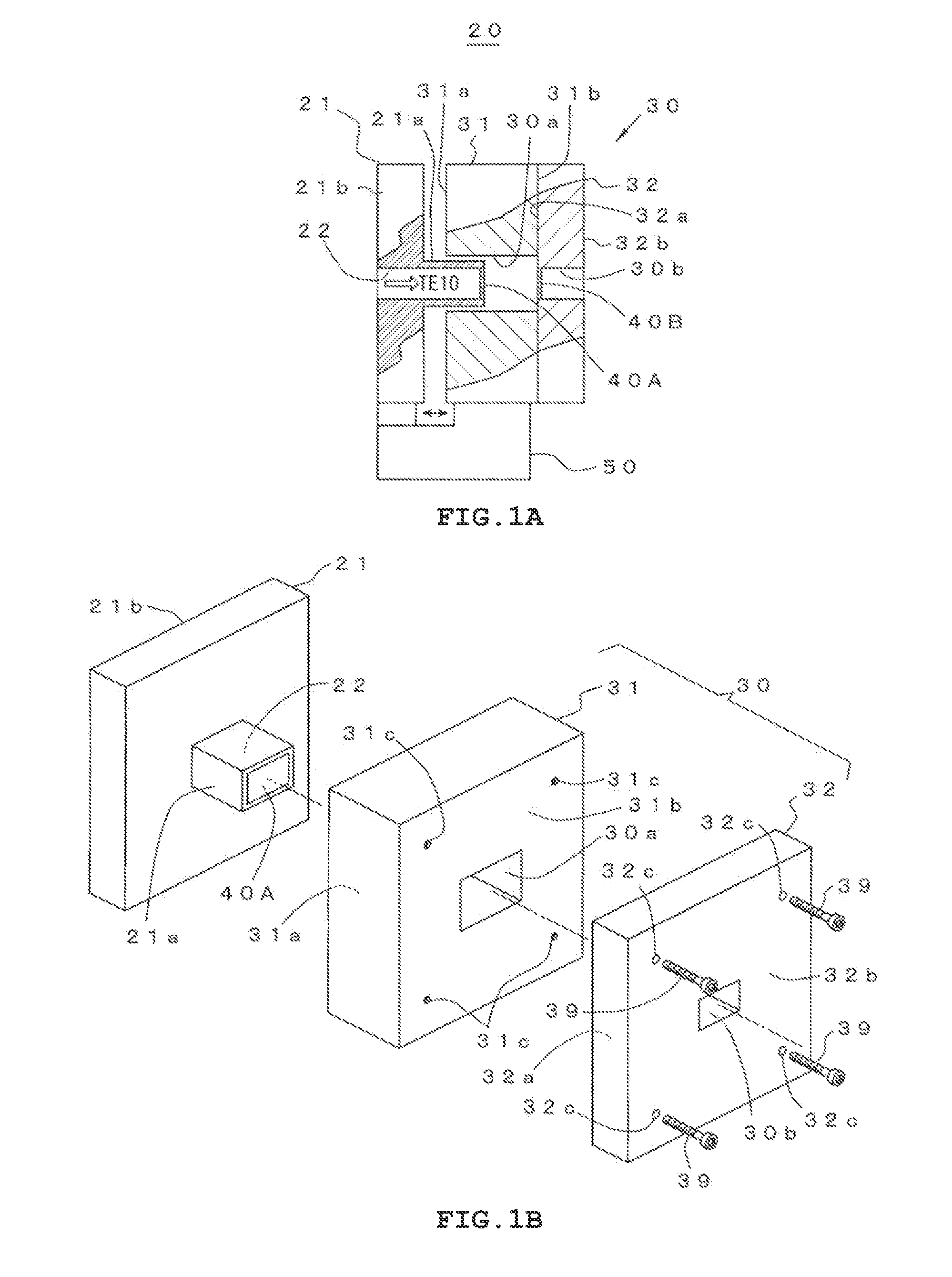
[0070]As shown in side view of FIG. 1A, a millimeter waveband filter 20 has a first waveguide 21, a second waveguide 30, a pair of electric wave half mirrors 40A and 40B, and a support mechanism 50.

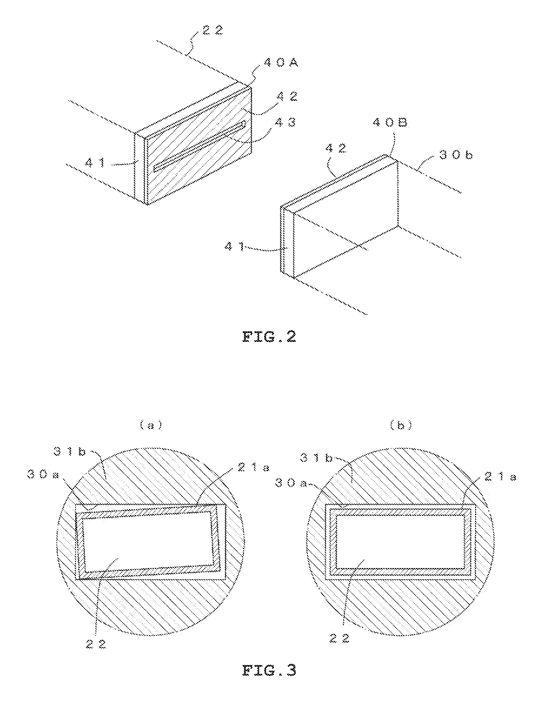
[0071]The first waveguide 21 has as square cylindrical portion 21a and a flange 21b provided at one end of the square cylindrical portion 21a. Inside the square cylindrical portion 21a, a transmission line 22 which has a size (for example, a size of a×b=2.032 mm×1.016 mm) allowing electromagnetic waves in a predetermined frequency range (for example, 110 to 140 GHz) of a millimeter waveband to propagate in a TE10 mode (single mode) is formed from one end to the other end.

[0072]The second waveguide 30 is formed such that a first transmission line 30a which has a size slightly (for example, 20 μm vertically and horizontally) g...


PUM


Abstract

A transmission line which allows electromagnetic waves in a predetermined frequency range of a millimeter waveband to propagate in a TE10 models formed by a first waveguide and a second waveguide. A resonator is formed by electric wave half mirrors fixed to the first waveguide and the second waveguide. The second waveguide has a structure in which a first transmission line forming body has a plate shape and has a square hole forming the first transmission line formed to pass therethrough from one surface toward an opposite surface, a second transmission line forming body has a plate shape and has a square hole forming the second transmission line formed to pass therethrough from one surface toward an opposite surface, and the first transmission line forming body and the second transmission line forming body are connectable and separable.

Description

TECHNICAL FIELD[0001]The present invention relates to a filter which is used in a millimeter waveband.BACKGROUND ART[0002]In recent years, there is an increasing need for the use of electric waves in response to a ubiquitous network society, and a wireless personal area network (WPAN) which realizes wireless broadband at home or a millimeter waveband wireless system, such as a millimeter-wave radar, which supports safe and secure driving starts to be used. An effort to realize a wireless system at a frequency greater than 100 GHz is actively made.[0003]In regard to second harmonic evaluation of a wireless system in a 60 to 70 GHz band or evaluation of a radio signal a frequency band over 100 GHz, as the frequency becomes high, the noise level of a measurement device and conversion loss of a mixer increase and frequency precision is lowered. For this reason, a high-sensitivity and high-precision measurement technology of a radio signal over 100 GHz has not been established. In the co...

Claims


Application Information

Patent Timeline
Patent Type & Authority Patents(United States)
IPC IPC(8): H01P1/201H01P1/207H01P5/02
CPCH01P1/201H01P5/024H01P1/207
Inventor KAWAMURA, TAKASHIOTANI, AKIHITOHASEGAWA, HIROSHI
Owner ANRITSU CORP
Why Eureka
Try Eureka