
Three-dimensional printer, three-dimensional image forming method, and three-dimensional image

a three-dimensional image and printer technology, applied in the field of three-dimensional printers, three-dimensional image forming methods, and three-dimensional images, can solve the problems of increasing the heat capacity of sheets, reducing the amount of heat applied to microcapsules, and reducing the raised amount of raised portions, so as to achieve the effect of higher density

Inactive Publication Date: 2015-10-20
CASIO COMPUTER CO LTD
View PDF8 Cites 9 Cited by
  • Summary
  • Abstract
  • Description
  • Claims
  • Application Information

AI Technical Summary

Benefits of technology

[0011]To solve the aforementioned problems, a three-dimensional printer according to the present invention includes: a first printed image forming unit configured to form a first printed image on one face of a thermally expandable sheet in which a thermally expandable layer is formed; a second printed image forming unit configured to form a second printed image on the other face of the thermally expandable sheet, the second printed image having a higher density as a thermal capacity of the thermally expandable sheet is larger; and a heat applying and expanding unit configured to apply thermal energy to the thermally expandable sheet to expand the thermally expandable layer.

Problems solved by technology

If, however, the thickness of the sheet (sheet base material) before the coating layer is formed is increased, that is, if the basis weight increases, there is a problem that the heat capacity of the sheet increases and thus the quantity of heat applied to the microcapsules decreases, resulting in that the raised amount of the raised portions decreases.
The heat capacity is increased not only by the problem of the increased basis weight of the sheet base material but also when a sheet made of another material is adhered to the sheet base material.
A large quantity of heat applied to the thermally expandable sheet, however, causes a failure such as thermal expansion of a non-printed region.

Method used


Image

  • Three-dimensional printer, three-dimensional image forming method, and three-dimensional image
  • Three-dimensional printer, three-dimensional image forming method, and three-dimensional image
  • Three-dimensional printer, three-dimensional image forming method, and three-dimensional image

Examples


first embodiment

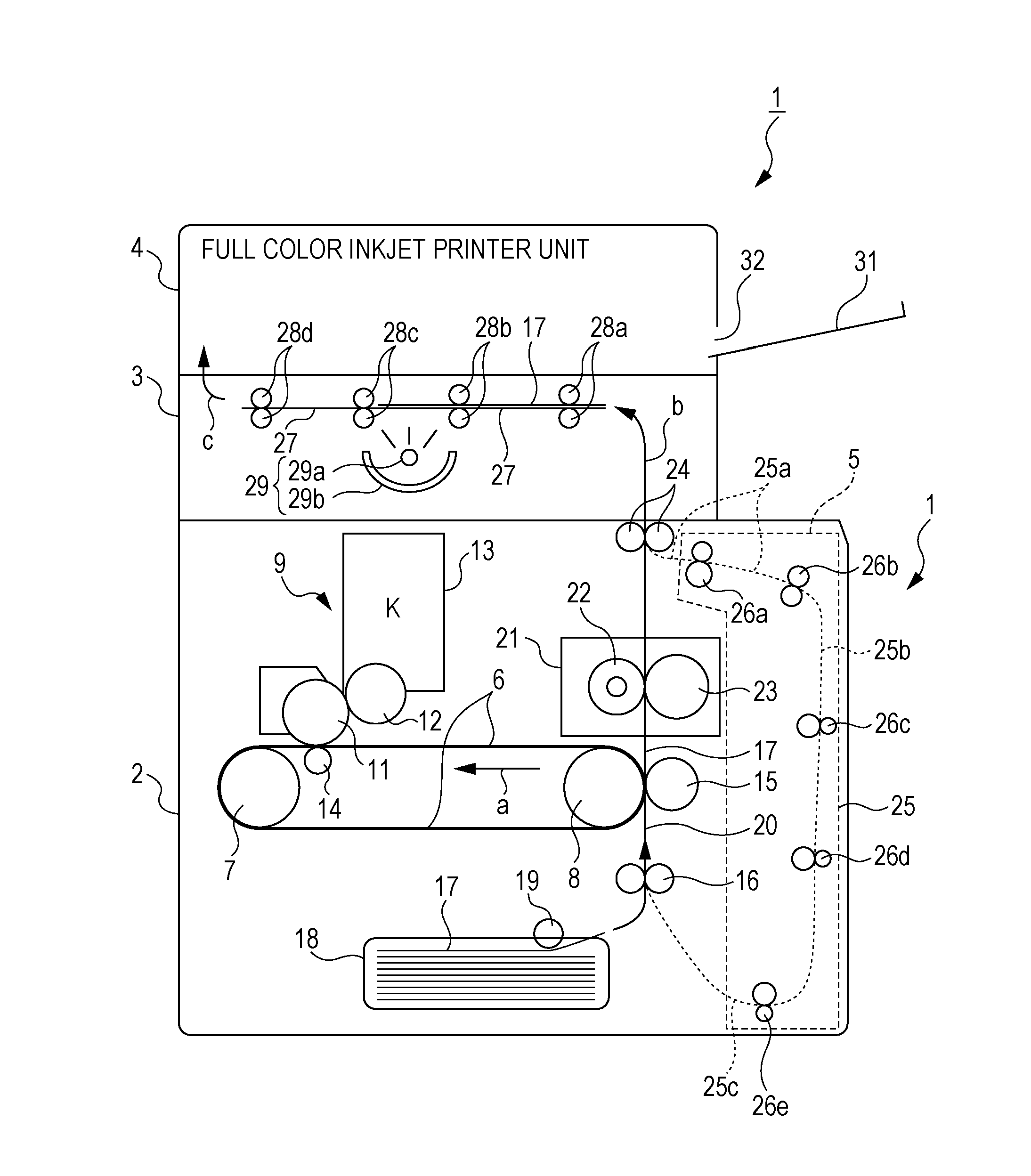
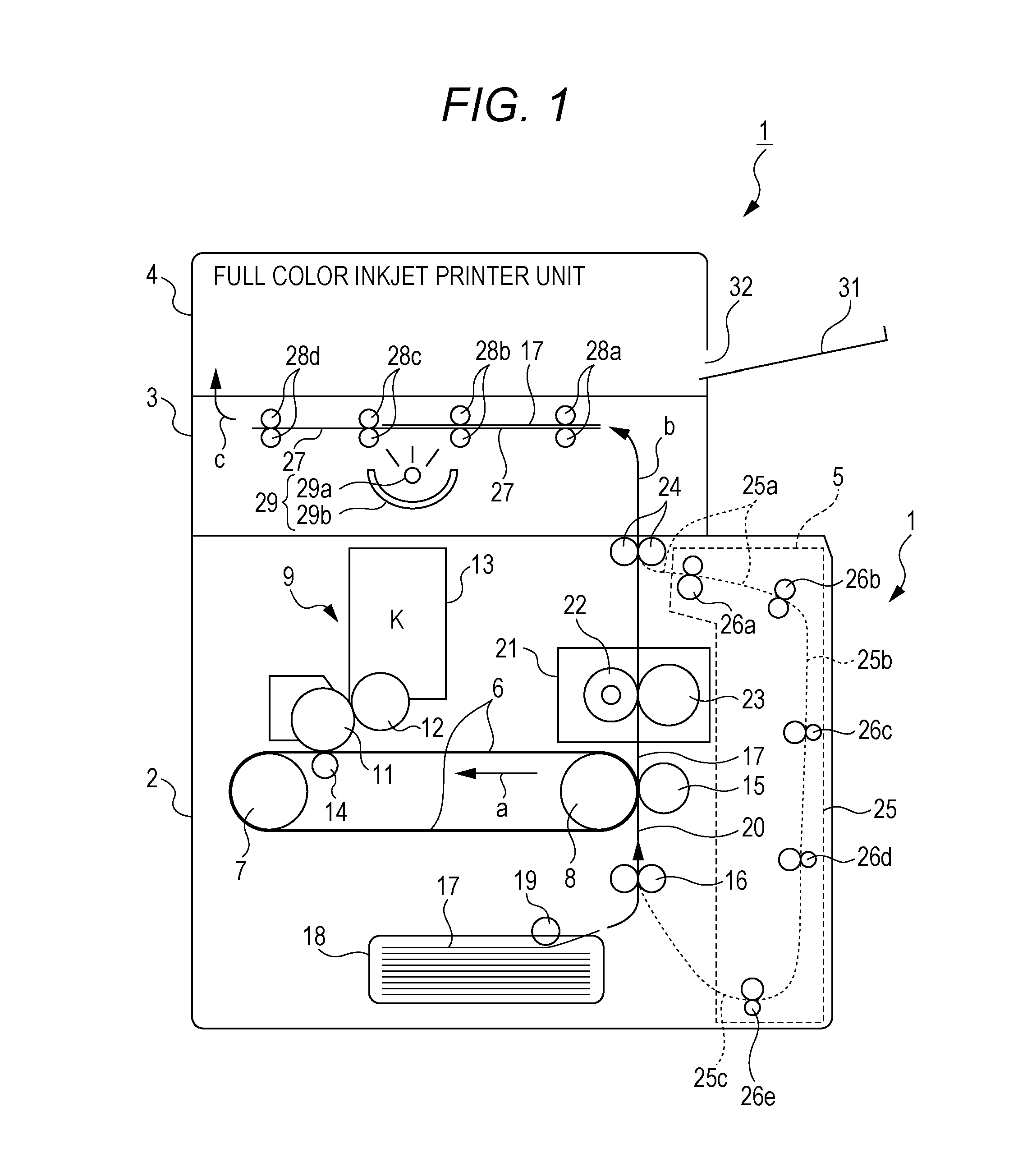
[0023]FIG. 1 is a cross-sectional view schematically illustrating an internal configuration of a three-dimensional printer according to a first embodiment. As illustrated in FIG. 1, the three-dimensional printer 1 includes a lowermost black toner printing unit 2, a thermal expansion processing unit 3 thereon, and an uppermost full-color inkjet printer unit (hereinafter simply referred to as an inkjet printer unit) 4.

[0024]The black toner printing unit 2 includes an endless transfer belt 6 extending in the horizontal direction at the center of the inside of the printer. The transfer belt 6 is looped around a driving roller 7 and a driven roller 8 while being tightly stretched by a stretching mechanism that is not illustrated, driven by the driving roller 7 to move circularly in the counterclockwise direction indicated by an arrow a in FIG. 1.

[0025]A photosensitive drum 11 of an image forming unit 9 is provided in contact with an upper surface of the transfer belt 6 moving circularly....


PUM

PropertyMeasurementUnit
densityaaaaaaaaaa
thermal capacityaaaaaaaaaa
thermal energyaaaaaaaaaa

Abstract

When a heat capacity of a recording medium having a base material coated with a foamable resin layer is larger than a normal heat capacity, to form a raised amount equal to that with the normal case with a normal heating quantity, a turned mirror image of the image is generated. The image is transferred onto the front face of the recording medium and fixed. The recording medium is reversed, and conveyed again to the transfer part. The turned mirror image is transferred onto the rear face of the recording medium and fixed. The recording medium is heated with the heat quantity equal to that in the normal case, and combination of heat absorbed by the turned minor image and heat absorbed by the image is transmitted to the foamable resin layer to expand the foamable resin layer.

Description

CROSS-REFERENCE TO RELATED APPLICATIONS[0001]This application claims the benefit of Japanese Patent Application No. 2013-184583 filed on Sep. 6, 2013 and Japanese Patent Application No. 2014-018807 filed on Feb. 3, 2014, which are hereby incorporated by reference herein in their entireties.BACKGROUND[0002]1. Technical Field[0003]The present invention relates to a three-dimensional printer configured to form a raised image on a thermally expandable sheet, a three-dimensional image forming method, and a three-dimensional image.[0004]2. Related Art[0005]In related art, JP 64-028660 A proposes a method for forming a three-dimensional image by forming a front-back reversed image of a desired image on a rear face, on which no thermally expandable coating layer is formed, of a thermally expandable sheet with an image forming material excellent in light absorption characteristics, irradiating the image forming side of the thermally expandable sheet with light to selectively heat an image pa...

Claims


Application Information

Patent Timeline
Patent Type & Authority Patents(United States)
IPC IPC(8): B41J11/00B41J3/60
CPCB41J11/002B41J3/60B41M3/06B41M3/16B41J11/00216B29C44/022B29C2035/0822B29C35/0266
Inventor MOTOYANAGI, YOSHIMUNE
Owner CASIO COMPUTER CO LTD
Learn More