Parts for crankshaft of internal combustion engine or compressor, crankshaft, internal combustion engine and compressor
a technology for internal combustion engines and crankshafts, which is applied in the direction of shafts, bearings, rotary machine parts, etc., can solve the problems of inability to complete balance, limited space for arranging lock up structures, and bulky machines, and achieve relative angular relationships among various parts, convenient insertion of crank pins, and easy manufacturing
- Summary
- Abstract
- Description
- Claims
- Application Information
AI Technical Summary
Benefits of technology
Problems solved by technology
Method used
Image
Examples
first embodiment
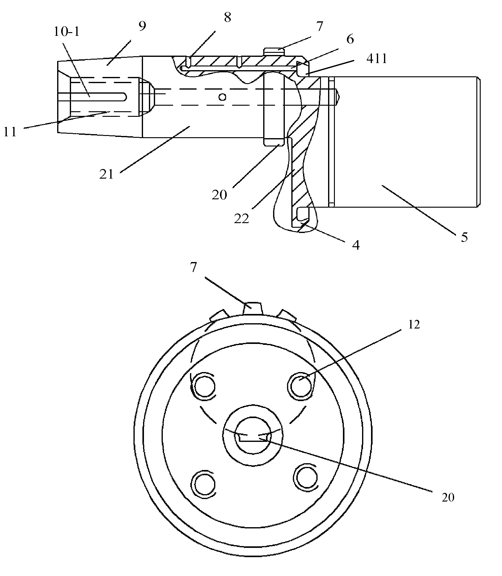
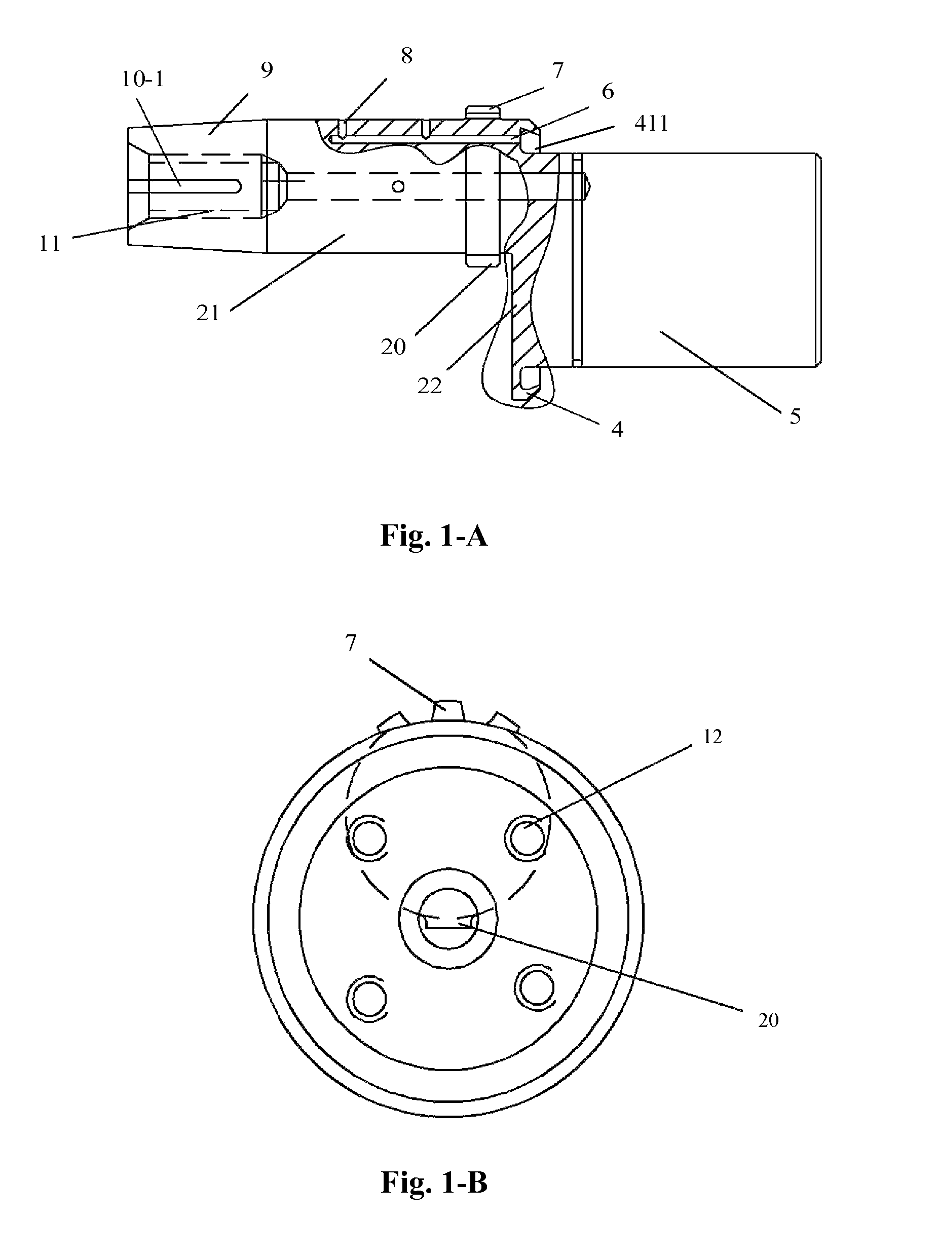
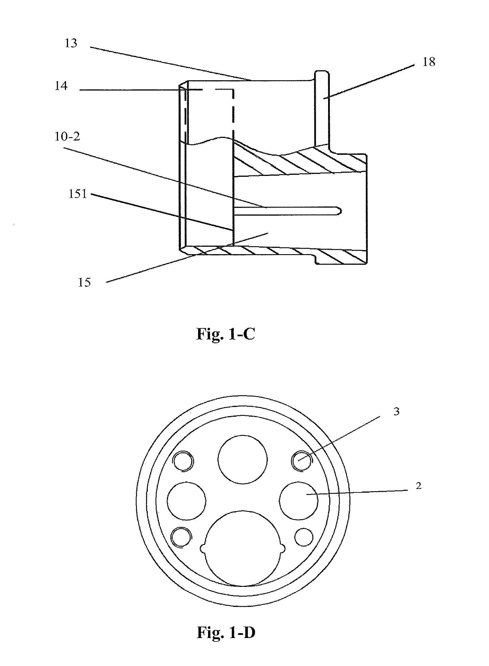
[0055]the invention provides a modular crankshaft of a miniature two-stroke single-cylinder engine. The modular crankshaft includes a single throw and a crank which is combined therewith, both of which are assembled together to form a complete crankshaft. FIG. 1 illustrates this modular crankshaft, wherein FIG. 1-A is a front view of the single throw of the modular crankshaft, FIG. 1-B is a right side view of the single throw shown in FIG. 1-A, FIG. 1-C is a front view of the crank of the modular crankshaft, FIG. 1-D is a left side view of the crank of the modular crankshaft, and FIG. 1-E is a front view of the modular crankshaft after being combined.
[0056]Reference is now made to FIG. 1-A. The single throw of the modular crankshaft includes three portions having axes in parallel with each other and connected in the following order: a single throw main journal 5, a first crank arm 22 and a crank pin 21. All of the three portions are cylindrical and have diameters different from each...
second embodiment
[0068]the invention provides a modular crankshaft used for a three-cylinder air compressor. The modular crankshaft comprises a single throw and a crank to be combined with the single throw, both of which are assembled together to form a complete crankshaft. FIG. 2 illustrates this modular crankshaft, wherein FIG. 2-A is a front view of the single throw of the modular crankshaft, FIG. 2-B is a front view of the crank of the modular crankshaft, and FIG. 2-C is a front view of the modular crankshaft after being combined.
[0069]Reference is now made to FIG. 2-A. The single throw of the modular crankshaft includes three portions having axes in parallel with each other and connected in the following order: a single throw main journal 28, a first crank arm 29 and a crank pin 31. The structure of the single throw is substantially the same as that in the above-described first embodiment, and only the difference therebetween will be described below.
[0070]As shown in FIG. 2-A, a circular boss, ...
third embodiment
[0078]In the third embodiment, it is also shown that a ring groove is provided on the single throw main journal 39 to serve as an oil groove 40. Meanwhile, oil orifices 41 that communicate the oil groove 40 with the main oil passage 44 are provided. Through this structure, lubrication oil can be fed into the main oil passage 44 from the oil groove 40. Besides, an inclined oil orifice 47 that communicates the surface of a cone 48 on the front end of the crank pin 46 with the main oil passage 44 is provided on the cone 48; an oil orifice 60 that communicates the surface of the crank main journal 52 and the inside diameter surface of the tapered hole 59 is provided on the crank. As shown in FIG. 3-E, when the assembly is completed, the inclined oil orifice 47 cooperates with the oil orifice 60 so as to feed oil to the bearing of the crank main journal 52.
PUM
 Abstract
Description
Claims
Application Information
 - R&D
- Intellectual Property
- Life Sciences
- Materials
- Tech Scout
- Unparalleled Data Quality
- Higher Quality Content
- 60% Fewer Hallucinations
Browse by: Latest US Patents, China's latest patents, Technical Efficacy Thesaurus, Application Domain, Technology Topic, Popular Technical Reports.
© 2025 PatSnap. All rights reserved.Legal|Privacy policy|Modern Slavery Act Transparency Statement|Sitemap|About US| Contact US: help@patsnap.com


