
Composite molded lens and method for producing the same

a technology lens barrels, which is applied in the field of composite molded lenses, can solve the problems of difficult to form a positioning or alignment face, difficult to align the position of the molded lens in the lens frame or the lens barrel, and improve the accuracy of centering the molded lens, so as to achieve excellent bonding performance between the lens body and the lens fram

Inactive Publication Date: 2015-10-20
FUJIFILM CORP
View PDF12 Cites 4 Cited by
  • Summary
  • Abstract
  • Description
  • Claims
  • Application Information

AI Technical Summary

Benefits of technology

The present invention provides a composite molded lens with excellent bonding performance between its joint surface and a method for producing it. The lens body and lens frame are tightly bonded together through the use of projections and / or grooves that extend radially towards the outer peripheral edge of the lens body. This improves the overall quality and performance of the lens.

Problems solved by technology

However, it is difficult to form a positioning or alignment face, which is perpendicular to the optical axis, and an outer peripheral end face, which is fitted into a lens frame, of the molded lens.
Hence, it is difficult to align the position of the molded lens in the lens frame or a lens barrel or to improve the accuracy of centering the molded lens.
Recently, small molded lenses and large-diameter molded lenses have been developed and there has been a tendency to reduce the lens thickness relative to outer-diameter dimensions.
This makes it difficult to attach the lens frame to the molded lens.
As a result, the accuracy of attaching the lens frame or the like to the molded lens is further reduced.
In a case where the lens frame is injection-molded around the outer periphery of the press-formed lens body, the problem arises that the bonding performance (tight bonding performance) of a joint surface or interface between the outer periphery of the lens body and the lens frame is insufficient.
The insufficient bonding performance may result in separation of the lens frame from the lens body due to difference in expansion, which is caused by a change in environment temperature, or a curve or twist at the time of attaching the optical element device to a lens barrel.

Method used


Image

  • Composite molded lens and method for producing the same
  • Composite molded lens and method for producing the same
  • Composite molded lens and method for producing the same

Examples


first embodiment

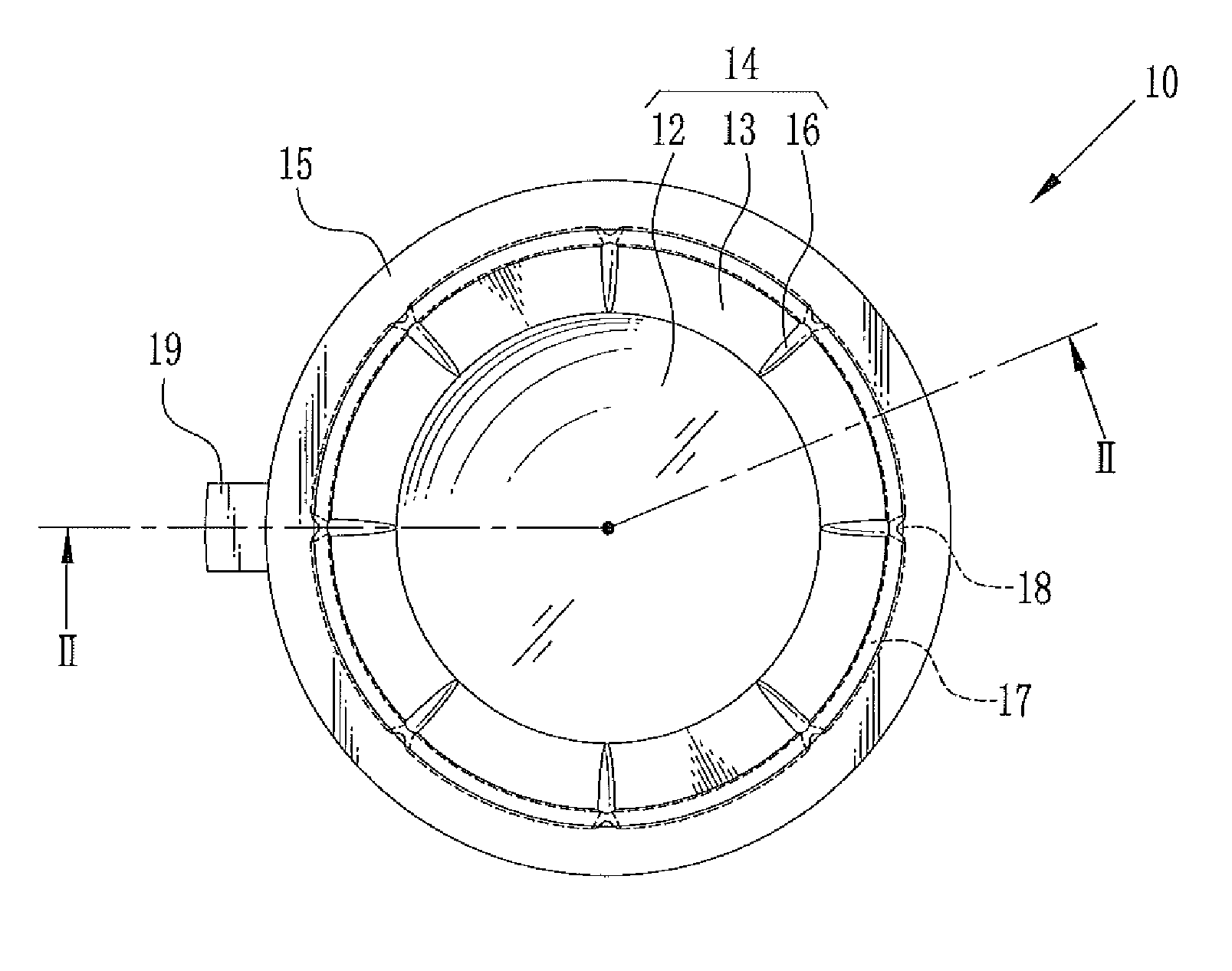
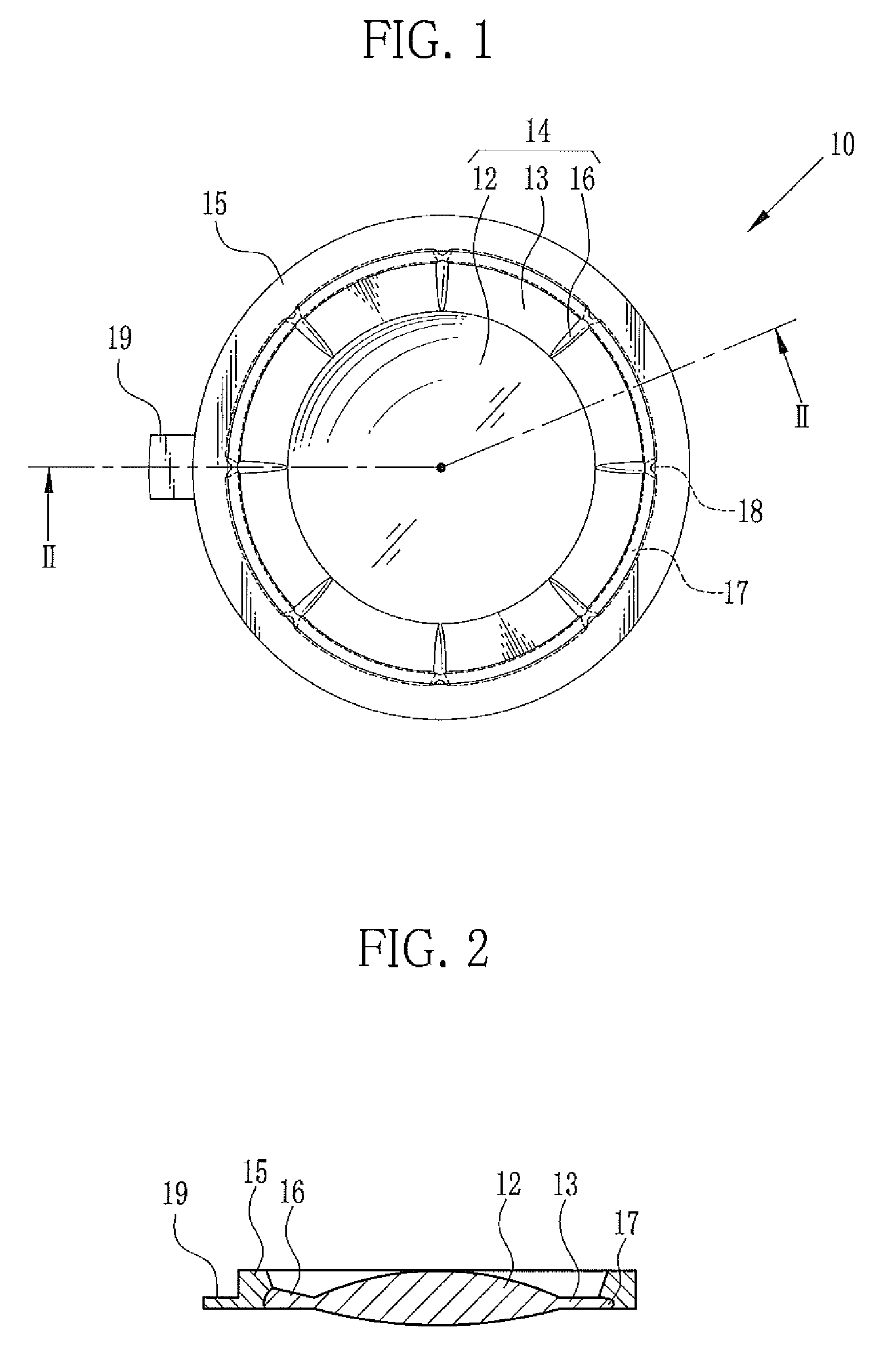
[0035]In FIGS. 1 and 2, a composite molded lens 10 comprises a lens body 14 and a lens frame (frame) 15. The lens body 14 is made by press-forming or press-molding a transparent preform. The lens frame 15 is made by injection molding. The lens body 14 has a lens portion 12 and a flange portion 13 surrounding the lens portion 12. The lens frame 15 is made from resin such as PMMA or PC through injection molding. The lens frame 15 is tightly joined to an outer peripheral portion of the flange portion 13. Note that opaque resin is commonly used for the lens frame 15. A gate portion 19 is formed due to the injection molding. The gate portion 19 is removed later as necessary.

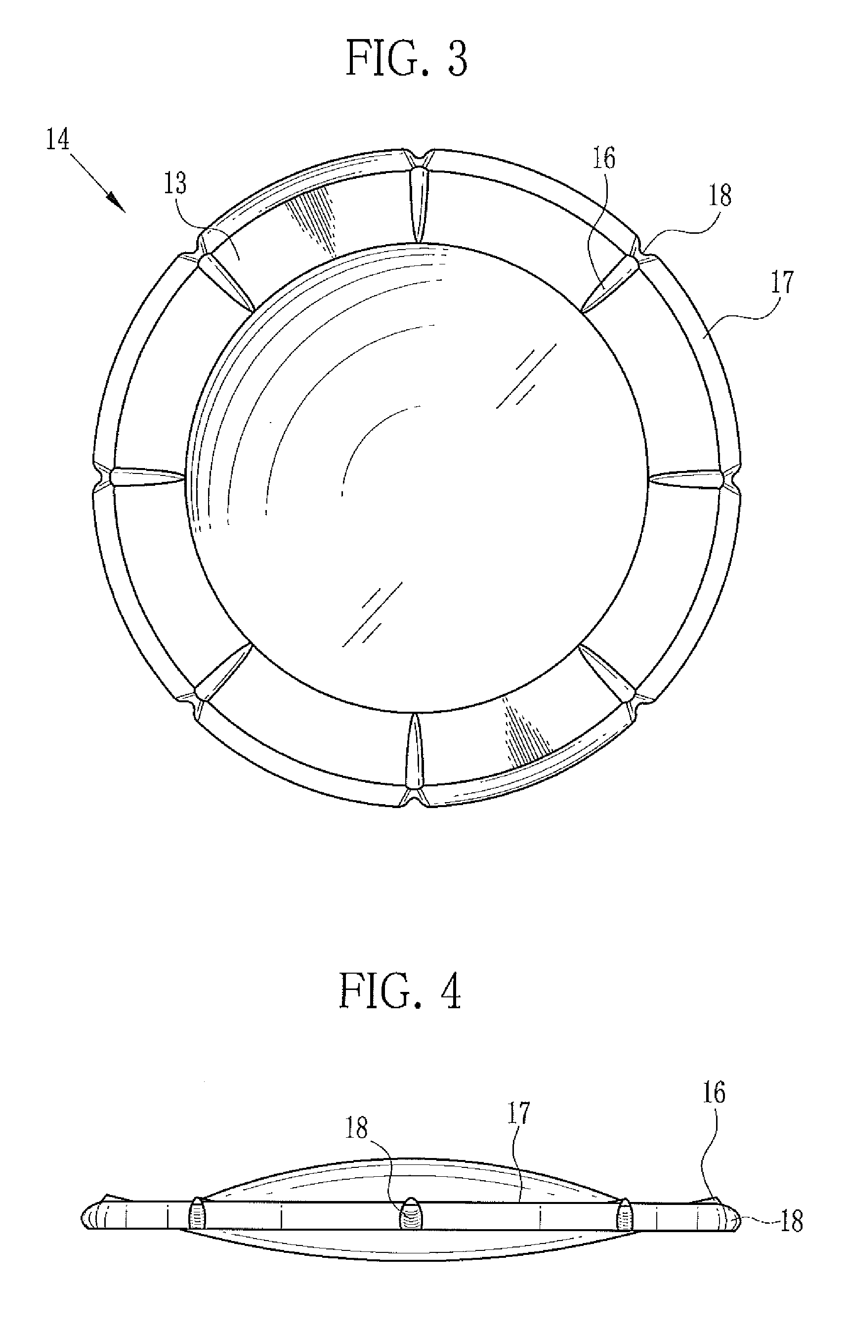
[0036]In FIGS. 3 and 4, there are eight projections 16 extending radially at 45° intervals on one surface of the flange portion 13 of the lens body 14. A planar shape of the projection 16 has a flat semi-ellipsoidal shape. A cross-section of the projection 16 has an upper convex segmental shape or a semi-ellipsoidal s...

second embodiment

[0043]In a second embodiment shown in FIGS. 8 to 12, the projections are formed on each surface of the flange portion. The positions of the projections on the top surface correspond to or coincide with those of the projections on the bottom surface. Note that the same reference numbers are used for the same parts as in the first embodiment. In FIGS. 8 and 9, a mold 30 is composed of a first mold 31 and a second mold 34. A gate opening 39 is formed in the second mold 34. The first mold 31 is the same as the first mold 21 of the first embodiment except that the lower edge of the first mold 31 is cut away by the thickness of the gate opening 39. The first mold 31 is formed with the transfer surface 22, the flange forming surface 23, the frame forming cavity 25, and the eight depressed portions 26. As shown in FIG. 9, the shape of the second mold 34 is the same as that of the first mold 21 of the first embodiment. The second mold 34 is formed with the transfer surface 27, a flange formi...

third embodiment

[0046]In a third embodiment shown in FIGS. 13 and 14, the projections 16 on the top surface of a flange portion 53 of a lens body 51 are shifted by ½ pitch (rotated by 22.5°) from the projections 46 on the bottom surface thereof. Thereby recesses 58a and 58b are formed alternately on the outer peripheral end face of an outer peripheral portion 57 of the flange portion 53. The recesses 58a and 58b are staggered from each other in an up-and-down direction. The recesses 58a and 58b make the free curved shape of the outer peripheral end face complex. As a result, the bonding force of the lens frame to the lens body 51 is further strengthened. Note that only the lens body 51 is depicted in FIGS. 13 and 14 because the lens frame is apparent from FIGS. 1 and 2.


PUM

PropertyMeasurementUnit
heightaaaaaaaaaa
depthaaaaaaaaaa
optical performanceaaaaaaaaaa

Abstract

In a composite molded lens, a press-formed lens body is integral with an injection-molded lens frame. The lens body has a lens portion and a flange portion surrounding the lens portion. Eight projections are radially formed on a top surface of the flange portion. The height of the projection increases toward an outer peripheral edge side of the flange portion. A recess is formed on an outer peripheral edge face of the flange portion and located at a position on a line extending from the projection. The recess increases torsional resilience of a joint surface between the lens body and the lens frame and strengthens bonding force there between.

Description

CROSS-REFERENCE TO RELATED APPLICATIONS[0001]This application is a Continuation of PCT International Application No. PCT / JP2012 / 080597 filed on Nov. 27, 2012, which claims priority under 35 U.S.C. §119 (a) to Japanese Patent Application No. 2012-051227, filed Mar. 8, 2012. Each of the above application(s) is hereby expressly incorporated by reference, in its entirety, into the present application.BACKGROUND OF THE INVENTION[0002]1. Field of the Invention[0003]The present invention relates to a composite molded lens formed by press-forming and injection molding and a method for producing a composite molded lens.[0004]2. Description Related to the Prior Art[0005]A digital camera, a mobile terminal with a camera, or the like uses a taking lens to form an image of a subject on an image sensor. A projector uses a projector lens to project an image, which is displayed on a liquid crystal display, onto a screen. A molded lens is generally used as an optical lens such as the taking lens or ...

Claims


Application Information

Patent Timeline
Patent Type & Authority Patents(United States)
IPC IPC(8): G02B7/02B29C45/14B29C69/02B29C43/02G02B3/00G02B27/10C03B11/08B29K101/12B29L11/00B29L12/00B29L31/00
CPCG02B7/02B29C43/021B29C45/14311B29C45/14336B29C69/02C03B11/08G02B3/00G02B7/022B29K2101/12B29L2011/0016B29L2012/00B29L2031/764C03B2215/06C03B2215/49C03B2215/73C03B2215/79B29D11/00538B29D11/00432
Inventor KOIKE, KAZUMIWATANABE, SEIICHIFUJIWARA, TAKAYUKIHIRAKI, YASUHITO
Owner FUJIFILM CORP
Learn More