Hydraulic system and wind turbine generator provided therewith

a technology of hydropower system and wind turbine, which is applied in the direction of rotors, greenhouse gas reduction, fluid couplings, etc., can solve the problems of high installation cost of heaters, and difficulty in adjusting blade pitch or blade control, so as to improve low-temperature startability

Inactive Publication Date: 2015-10-27
MITSUBISHI HEAVY IND LTD
View PDF30 Cites 6 Cited by
  • Summary
  • Abstract
  • Description
  • Claims
  • Application Information

AI Technical Summary

Benefits of technology

[0011]In view of such a conventional technical problem, it is an object of the present invention to provide a hydraulic system (hydraulic actuation system such as a hydraulic cylinder), which avoids an overloaded state at startup to enable low-temperature, fast startup and maintaining of the temperature with low-cost means in order to improve low-temperature startability, and a wind turbine generator provided therewith.
[0018]Since no load in the hydraulic main line on the hydraulic pump discharge side is confirmed from the pressure of the pressure sensor before startup, an overload that conventionally occurs due to a flow of excess current in the hydraulic pump at startup can be avoided.
[0019]Further, the control device receives a pressure detection signal upon startup of the hydraulic system, performs so-called PWM control to turn on / off a pulse controlled bypass valve so that the pump power of the hydraulic unit will become the maximum in order to rise oil temperature in the hydraulic main line on the hydraulic pump discharge side, and further controls the pump discharge pressure and the flow rate to be equal to or smaller than preset specified values. This enables an operation at the maximum pump power value or smaller at all times, and hence oil temperature can rise efficiently.
[0020]Thus, PWM control to turn on / off the pulse controlled bypass valve is performed, and this enables low-temperature startup in a relatively short time. Therefore, high installation costs conventionally required for components such as the heater are not needed, resulting in a reduction in the device cost.
[0021]Further, the present invention comprises a variable flow valve in the bypass path, wherein the control device controls the bypass flow rate using the variable flow valve to rise the temperature, so that flow rate control can be performed by a flow restrictor of the variable flow valve at a set point with the maximum pump power value or smaller at all times while detecting pressure in the hydraulic main line by means of the pressure sensor, thereby enabling a stable operation at the maximum pump power at all times, oil temperature to rise efficiently, and low-temperature startup in a relatively short time. Therefore, high installation costs conventionally required for components such as the heater are not needed, resulting in a reduction in the device cost.
[0022]Further, in the above invention, the temperature sensor for detecting the temperature of the oil and inputting the temperature detection value to the control device, wherein when the temperature detection value is lower than a predetermined temperature, the control device circulates oil in the bypass path while controlling the flow rate control means, and when the temperature detection value reaches the predetermined temperature, the control device performs control to stop oil circulation in the bypass path. Thus, when the temperature of the hydraulic main line reaches the lowest actuation temperature of the equipment, the bypass path is closed to apply pressure to the hydraulic main line, enabling the normal operation.

Problems solved by technology

However, the method using such a conventional heater 30 takes three to four hours to rise the oil temperature from −30 degrees C. to −10 degrees C. at startup, for example, thus requiring a lot of time and the installation cost of the heater 30.
Further, in the hydraulic system for wind turbine blade pitch actuation as shown in FIG. 6, if some load is left in the hydraulic system when the hydraulic system (hydraulic pump) is actuated at startup, excess current T flows through a motor 5 suddenly for a short time as shown in FIG. 7 to increase the load on the hydraulic system (hydraulic pump), resulting in an overload.
If this overloaded state at startup is repeated, a problem can occur with wind turbine blade pitch or blade control.

Method used


Image

  • Hydraulic system and wind turbine generator provided therewith
  • Hydraulic system and wind turbine generator provided therewith
  • Hydraulic system and wind turbine generator provided therewith

Examples


first embodiment

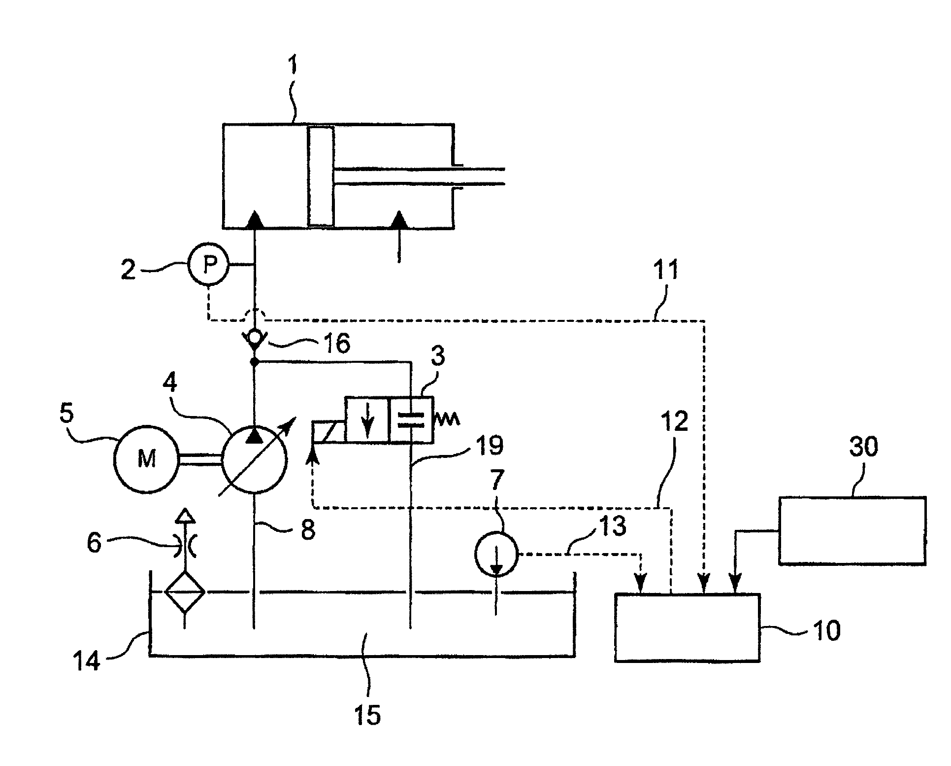
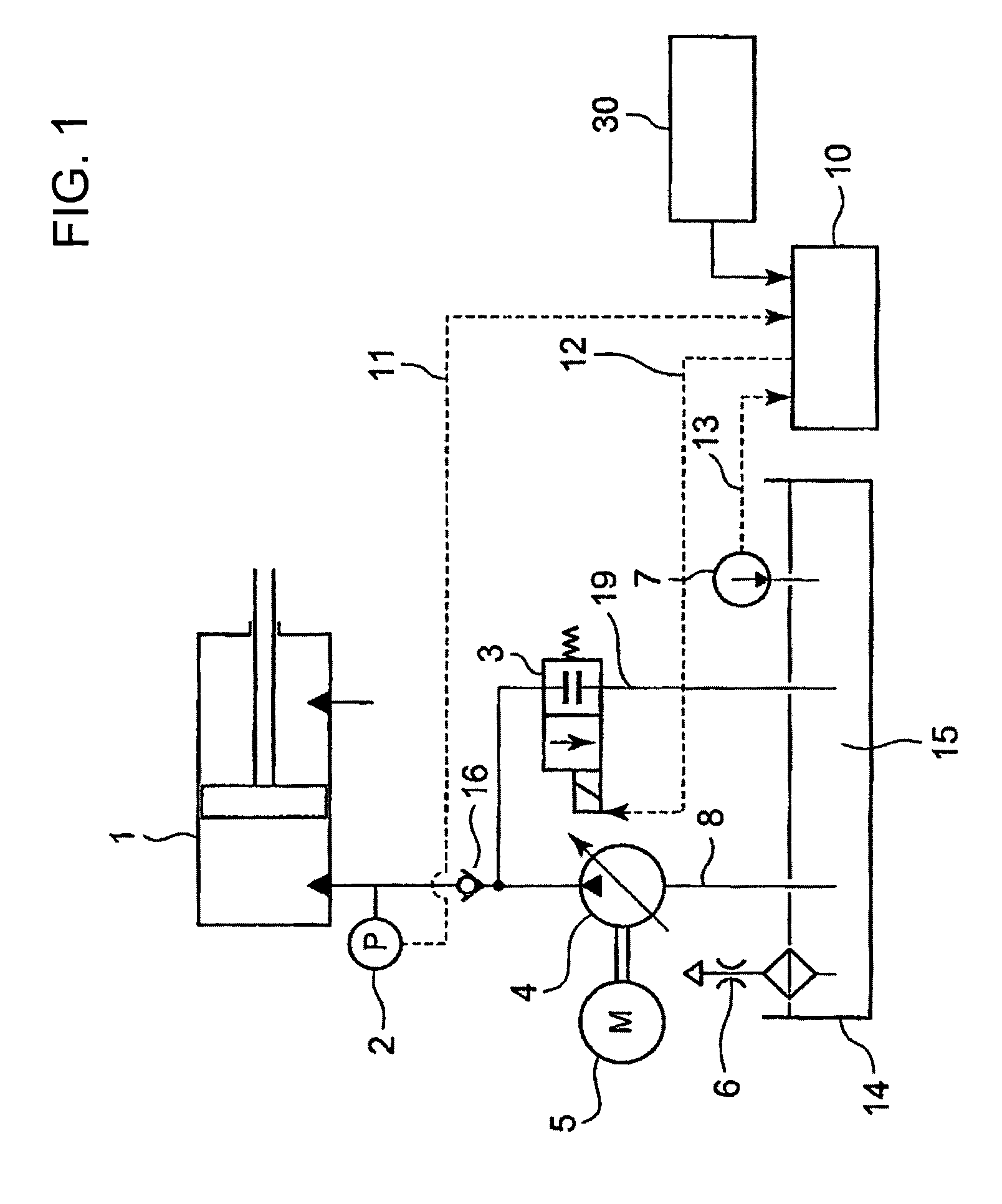
[0033]FIG. 1 is a system diagram of a starter in a hydraulic system for wind turbine blade pitch actuation according to a first embodiment of the present invention.

[0034]In FIG. 1, a hydraulic unit for blade pitch actuation (hydraulic actuation system such as a hydraulic cylinder) designated by reference numeral 1 is supplied with oil 15 stored in a hydraulic tank 14 through a hydraulic main line 8.

[0035]A hydraulic pump 4 to be driven by a motor 5 is placed in the hydraulic main line 8, and the oil 15 in the hydraulic tank 14 is fed by the hydraulic pump 4 into the hydraulic unit 1 through the hydraulic main line 8. A check valve 16 capable of feeding oil only on the side of the hydraulic unit 1 is provided in the hydraulic main line 8 (where a proportional valve, not shown, is provided in the inlet of the check valve 16 to prevent oil from flowing into a cylinder of the hydraulic unit when a bypass valve 3 is turned off). Note that an air breather provided in the hydraulic tank 14...

second embodiment

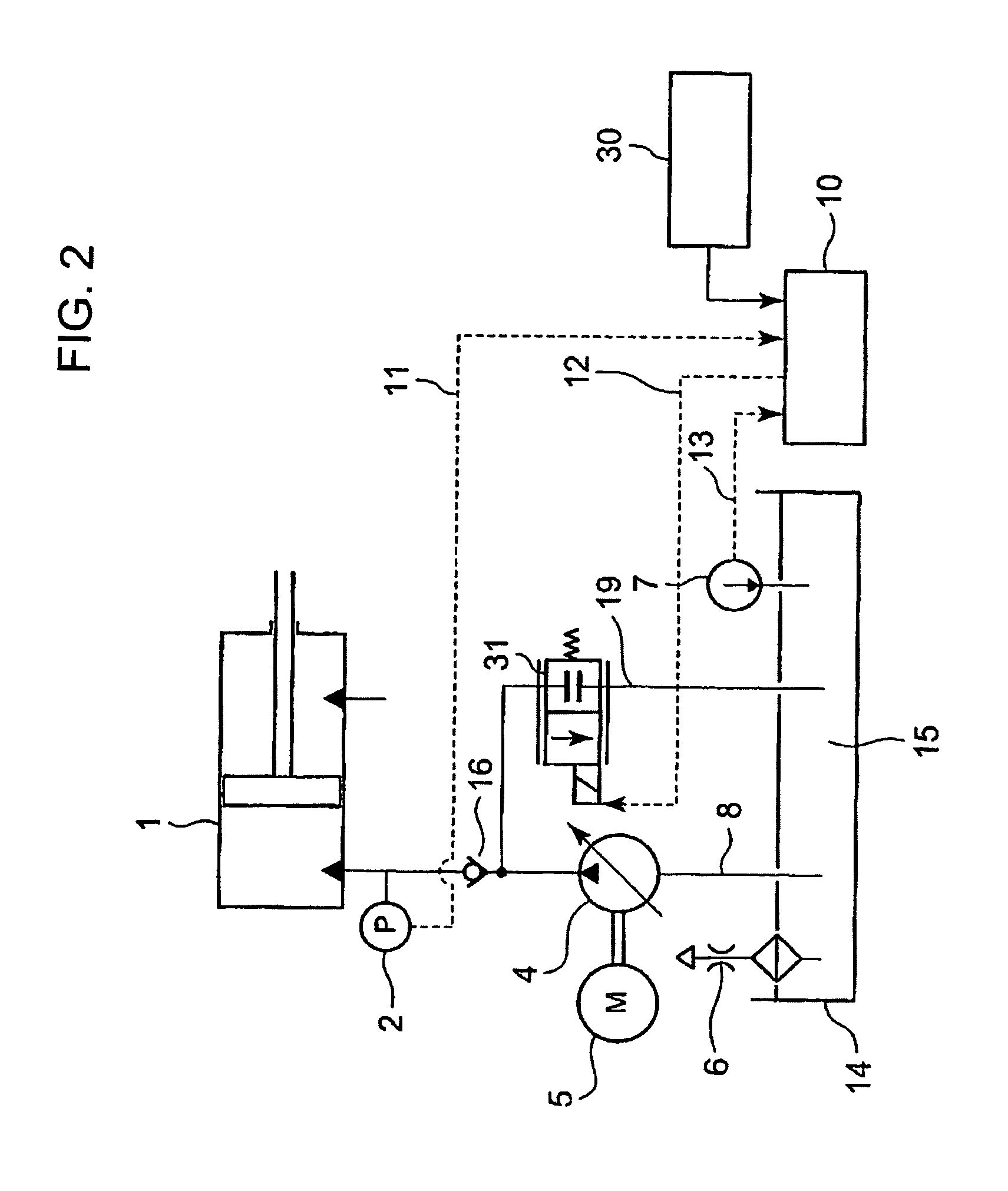
[0055]FIG. 2 is a system diagram of a starter in a hydraulic system for wind turbine blade pitch actuation according to a second embodiment of the present invention.

[0056]This second embodiment differs from the first embodiment in that a variable flow valve 31 is provided in the bypass path 19 to make the flow restriction in the bypass path 19 variable.

[0057]In other words, in a flowchart of FIG. 4 showing the operation of the second embodiment, step (5) is different from that in the first embodiment, and the other steps are the same.

[0058]In step (5), a pressure detection signal from the pressure sensor 2 is received after startup of the hydraulic system to change the amount of flow restriction (throttle) of the variable flow valve 31 in the hydraulic unit 1 in order to control flow path resistance of the bypass path 19.

[0059]Thus, since the flow rate is controlled by the throttle so that it will be located at a point (specified pressure P0) on the preset maximum power generation l...


PUM


Abstract

There is provided a hydraulic pump startup control device in a hydraulic system, which avoids an overloaded state at startup to enable low-temperature, fast startup and maintaining of the temperature with low-cost means in order to improve low-temperature startability. A bypass path 19 is placed in parallel with a hydraulic main line from a hydraulic tank, and the downstream of the bypass path is made merged with the hydraulic main line. A bypass valve 3 that opens or closes the bypass path is provided in the bypass path, and a pressure sensor is provided in the inlet of a hydraulic unit in the hydraulic main line. Further, a control device 10 to which a pressure detection value in the hydraulic main line is input from the pressure sensor to open the bypass valve based on the pressure detection value upon startup of the hydraulic unit. The control device repeats on-off control to circulate oil in the bypass path while keeping the pump discharge pressure and the flow rate to open the bypass path at startup so that the actuation power of the hydraulic unit will become the maximum in order to rise the hydraulic temperature of the hydraulic main line.

Description

BACKGROUND OF THE INVENTION[0001]1. Field of the Invention[0002]The present invention relates to a hydraulic (actuation) system applied to wind turbine blade pitch control or the like and adapted to supply oil from a hydraulic tank into a hydraulic unit for blade pitch control (hydraulic actuation system such as a hydraulic cylinder) through a hydraulic main line by means of a hydraulic pump placed in the hydraulic main line in order to actuate the hydraulic unit with the oil, and a wind turbine generator provided therewith.[0003]2. Description of the Related Art[0004]FIG. 6 shows the outline of a hydraulic (actuation) system of a hydraulic unit for wind turbine blade pitch actuation, in which the hydraulic unit for blade pitch actuation designated by reference numeral 1 is supplied with oil 15 stored in a hydraulic tank 14 through a hydraulic main line 8.[0005]A hydraulic pump 4 to be driven by a motor 5 is placed in the hydraulic main line 8, and the oil 15 in the hydraulic tank 1...

Claims


Application Information

Patent Timeline
Patent Type & Authority Patents(United States)
IPC IPC(8): F03D7/02F03D9/00F03D9/02
CPCF03D7/02F03D9/00F03D9/02Y02E10/723F03D9/10Y02E10/72Y02P80/10Y02E70/30
Inventor NOMAGUCHI, HIROYUKIYUGE, ATSUSHIHAYASHI, TOSHIKAZU
Owner MITSUBISHI HEAVY IND LTD
Why Eureka
Try Eureka