
Hybrid electric vehicle
a hybrid electric vehicle and electric vehicle technology, applied in the direction of electric generator control, automatic control system, electric generator control, etc., can solve the problems of not being able to directly “jump start” and the generators without switching resistance are not self-exciting, and the effect of reducing the number of sr (switched reluctance) is not good,
- Summary
- Abstract
- Description
- Claims
- Application Information
AI Technical Summary
Benefits of technology
Problems solved by technology
Method used
Image

Examples
Embodiment Construction
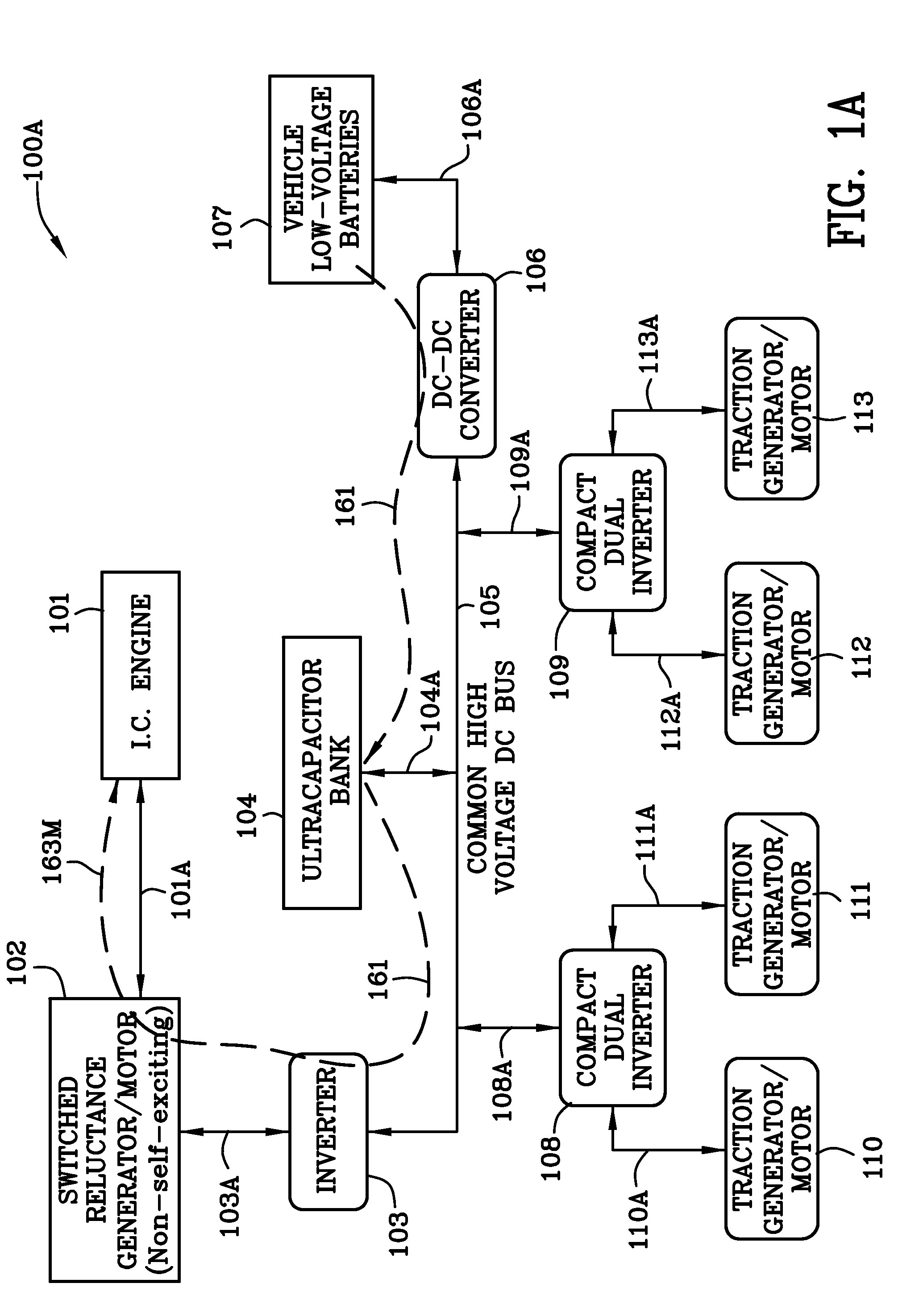
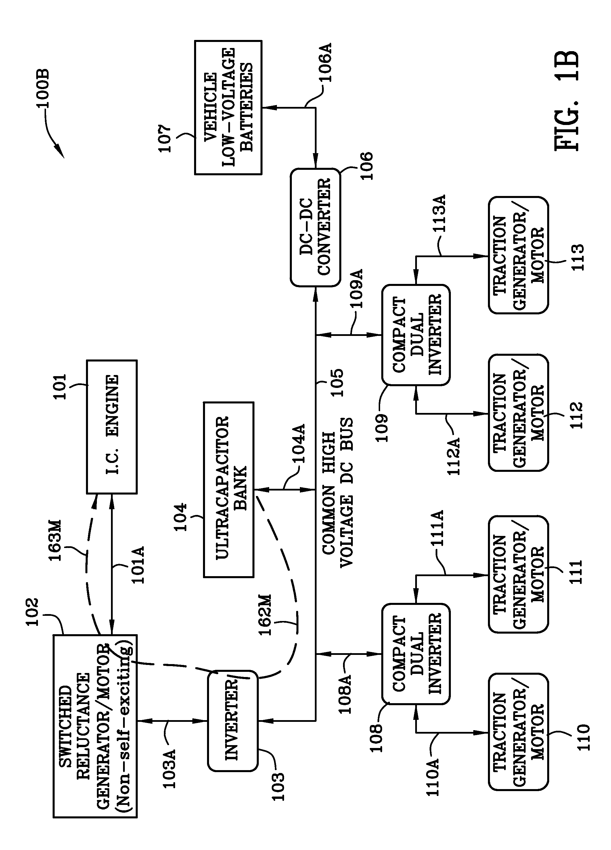
[0069]FIG. 1A is schematic illustration 100A of a hybrid electric vehicle illustrating, inter alia, the condition wherein the ultracapacitor bank 104 is charged from the 24-volt batteries 107 after a prolonged shut-down of the hybrid electric vehicle. FIGS. 1A-1H, inclusive, use many of the same reference numerals and they have the same meaning. Once an element is described in connection with a given reference numeral it will generally not be described again in connection with a subsequent drawing figure to avoid repetition. Reference numeral 161 indicates a dashed line illustrating energy flow along path 161 from the low voltage batteries 107 through the DC-DC converter 106 to the ultracapacitor bank 104, the bidirectional power inverter 103, and the non self-excited switched reluctance generator / motor operating in the motor mode and to the internal combustion engine 101. DC-DC converter 106 is capable of handling 5 kW of power. If the ultracapacitor bank is charged to a sufficient...
PUM
 Abstract
Description
Claims
Application Information