Fuel cell separator and method for manufacturing the same

a technology of fuel cell separator and separator plate, which is applied in the direction of cell components, final product manufacturing, sustainable manufacturing/processing, etc., can solve the problem of limit the adhesive force obtained between the resin coating layer and its counterpart member, and achieve high corrosion resistance and seal durability.

Active Publication Date: 2015-11-03
TOYOTA JIDOSHA KK
View PDF12 Cites 0 Cited by
  • Summary
  • Abstract
  • Description
  • Claims
  • Application Information

AI Technical Summary

Benefits of technology

[0010]The present invention has been made based on the aforementioned experience. It is an object of the present invention to provide a fuel cell separator and a method for manufacturing the same, in which the fuel cell separator has a metal plate and an anticorrosion resin coating layer formed thereon, and adhesion between the resin coating layer and its counterpart member (for example, adhesion between the resin coating layer and a resin frame or between the resin coating layer and a gasket) is further increased, whereby the power generation performance and durability of a fuel cell unit to be manufactured are further increased.
[0012]When the resin coating layer has the aforementioned surface roughness, an anchoring effect is produced at the interface between the stacked layers, whereby adhesion between the resin coating layer and its counterpart member (for example, adhesion between the resin coating layer and a resin frame or between the resin coating layer and a gasket) would be increased, compared to a case in which the surface of the resin coating layer is flat. Thus, a fuel cell unit constructed with the fuel cell separator of the present invention can have high durability with little possibility of delamination or the like.
[0018]As described above, when electrodeposition coating is performed with the use of an electrocoating material including fillers, it is possible to form a dense, uniform resin coating layer and impart a desired roughness Ra to the surface of the resin coating layer formed.
[0021]According to the present invention, an improved fuel cell separator is provided, which has a metal plate and an anticorrosion resin coating layer formed thereon and which has high corrosion resistance and is capable of ensuring high seal durability over a long period of time when built into a fuel cell unit.

Problems solved by technology

They found that although a dense, uniform resin coating layer can be obtained through electrodeposition of a resin coating layer on the surface of a metal separator, there is a limitation in adhesive force obtained between the resin coating layer and its counterpart member; for example, adhesive force between the resin coating layer and a resin frame or between the resin coating layer and a gasket.

Method used


Image

  • Fuel cell separator and method for manufacturing the same
  • Fuel cell separator and method for manufacturing the same
  • Fuel cell separator and method for manufacturing the same

Examples


example 1

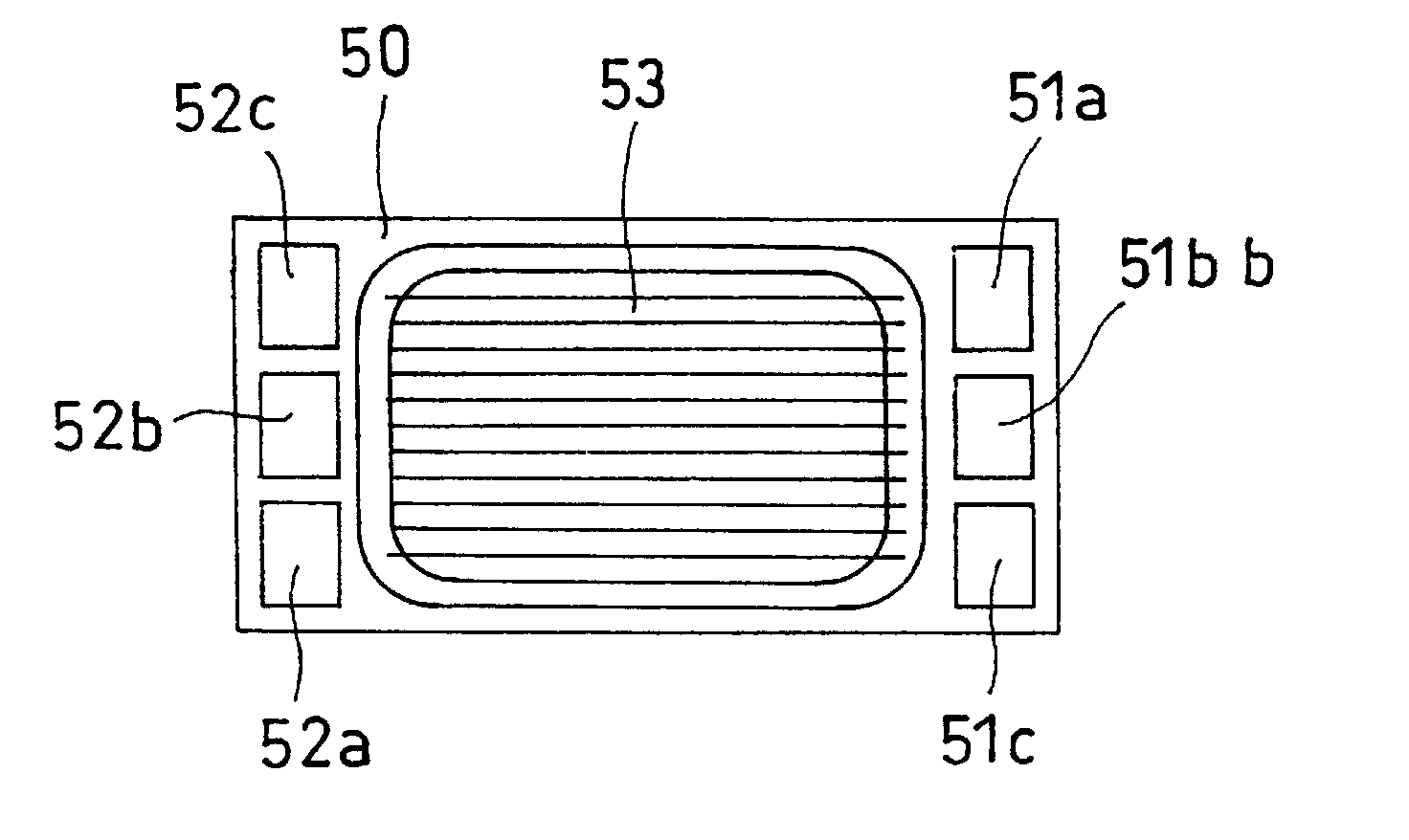
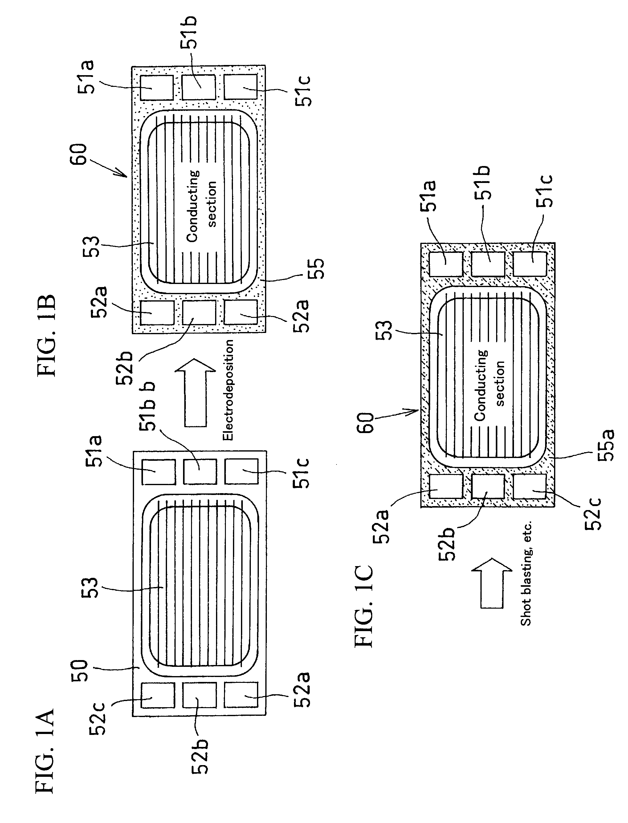
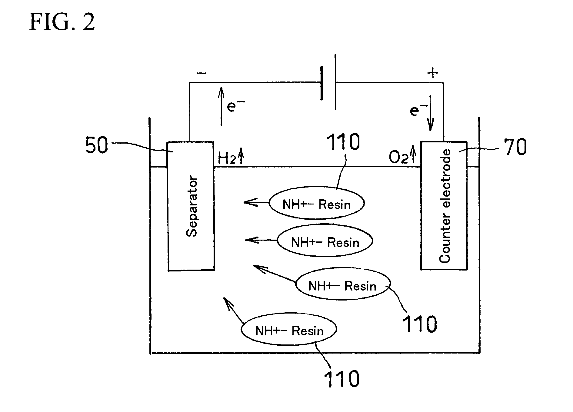
[0053]A region of gas flow channels (a conducting section) of a separator substrate made of austenitic stainless steel SUS was masked. With the masked separator substrate as a negative electrode and with a plate made of ferritic stainless steel SUS 430 as a positive electrode, the masked separator substrate was immersed in an electrodeposition bath containing a 20 mass % cationic electrocoating material (insuleed 4200: a product of Nippon Paint Co., Ltd.) that includes an aqueous polyamide imide resin, with the following conditions: a coating ratio of + / −electrodes of −1 / 2, an interelectrode distance of 15 cm, and a liquid temperature of 30° C. The voltage applied was gradually increased such that the voltage reached a predetermined level in five seconds. After having reached the predetermined level, the applied voltage was maintained for 115 to 145 seconds, so that cationic electrodeposition coating was performed. Then, the masking material was removed and baking at 200° C. was per...

example 2

[0056]A region of gas flow channels (a conducting section) of a separator substrate made of austenitic stainless steel SUS was masked. With the masked separator substrate as a negative electrode and with a plate made of ferritic stainless steel SUS 430 as a positive electrode, the masked separator substrate was immersed in three kinds of electrodeposition baths each containing a 20 mass % cationic electrocoating material (insuleed 4200: a product of Nippon Paint Co., Ltd.) that includes an aqueous polyamide imide resin, to which acrylic resin particles with a volume mean particle diameter of 50 to 100 nm accounting for 5 mass %, 10 mass %, and 15 mass %, respectively, were added as fillers, with the following conditions: a coating ratio of + / −electrodes of −1 / 2, an interelectrode distance of 15 cm, and a liquid temperature of 30° C. The voltage applied was gradually increased such that the voltage reached a predetermined level in five seconds. After having reached the predetermined ...


PUM

PropertyMeasurementUnit
surface roughness Raaaaaaaaaaa
particle diameteraaaaaaaaaa
surface roughness Raaaaaaaaaaa

Abstract

A fuel cell separator 60 having a metal plate and an anticorrosion resin coating layer 55 formed thereon is provided, with which adhesion between the resin coating layer 55 and its counterpart member is further increased and the durability of a fuel cell unit is improved. In forming the fuel cell separator 60 having a separator substrate 50 that is a metal plate and an anticorrosion resin coating layer 55 formed thereon, the resin coating layer 55 is formed such that it has a surface roughness Ra of 0.5 to 13.5 μm. Increasing the surface roughness will produce an anchoring effect, which will improve the adhesive force at the interface. The aforementioned surface roughness Ra can be obtained either with the use of fillers that are mixed into the resin coating layer 55 or with external force applied to the surface of the resin coating layer 55 by means of shot blasting, for example.

Description

BACKGROUND OF THE INVENTION[0001]1. Field of the Invention[0002]The present invention relates to a fuel cell separator and a method for manufacturing the same.[0003]2. Background Art[0004]As typical examples of fuel cells, polymer electrolyte fuel cells are known. FIG. 7 is a cross-sectional view illustrating an example of such a fuel cell, in which a membrane electrode assembly 3 having an electrolyte membrane 1 and a pair of electrode layers 2 each of which has a sequential stack of a catalyst layer 21 and a diffusion layer 22 and is formed on each side of the electrolyte membrane 1 is provided, and the opposite sides of the membrane electrode assembly 3 are sandwiched between separators 5,5 each having gas flow channels 4, whereby a single fuel cell unit is formed. An electrolyte membrane 1a protrudes beyond the periphery of the electrode layers 2, and a space between the protruding electrolyte membrane 1a and the separators 5 is filled with a gasket 6 as an adhesive having a sea...

Claims


Application Information

Patent Timeline
Patent Type & Authority Patents(United States)
IPC IPC(8): H01M8/04H01M4/82H01M8/02H01M8/10
CPCH01M8/0221H01M8/0206H01M8/0228H01M8/021H01M2008/1095Y02E60/50Y10T29/49115Y02P70/50C25D5/50C25D9/02H01M8/0239
Inventor WATANABE, YUSUKEKUROSAKI, YOSHINOBU
Owner TOYOTA JIDOSHA KK
Why Eureka
Try Eureka